

X-ray fiber diffraction modeling of structural changes of the thin filament upon activation of live vertebrate skeletal muscles
- PMID: 27857582
- PMCID: PMC5036664
- DOI: 10.2142/biophysics.6.13
X-ray fiber diffraction modeling of structural changes of the thin filament upon activation of live vertebrate skeletal muscles
Abstract
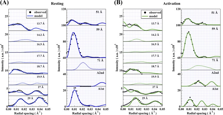
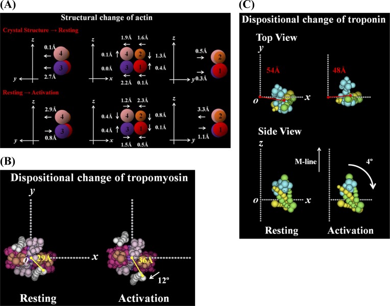
In order to clarify the structural changes of the thin filaments related to the regulation mechanism in skeletal muscle contraction, the intensities of thin filament-based reflections in the X-ray fiber diffraction patterns from live frog skeletal muscles at non-filament overlap length were investigated in the relaxed state and upon activation. Modeling the structural changes of the whole thin filament due to Ca2+-activation was systematically performed using the crystallographic data of constituent molecules (actin, tropomyosin and troponin core domain) as starting points in order to determine the structural changes of the regulatory proteins and actin. The results showed that the globular core domain of troponin moved toward the filament axis by ∼6 Å and rotated by ∼16° anticlockwise (viewed from the pointed end) around the filament axis by Ca2+-binding to troponin C, and that tropomyosin together with the tail of troponin T moved azimuthally toward the inner domains of actin by ∼12° and radially by ∼7 Å from the relaxed position possibly to partially open the myosin binding region of actin. The domain structure of the actin molecule in F-actin we obtained for frog muscle thin filament was slightly different from that of the Holmes F-actin model in the relaxed state, and upon activation, all subdomains of actin moved in the direction to closing the nucleotide-binding pocket, making the actin molecule more compact. We suggest that the troponin movements and the structural changes within actin molecule upon activation are also crucial components of the regulation mechanism in addition to the steric blocking movement of tropomyosin.
Keywords: Ca2+-regulation; Thin filament; X-ray fiber diffraction; skeletal muscle.
Figures


Similar articles
-
A comparison of muscle thin filament models obtained from electron microscopy reconstructions and low-angle X-ray fibre diagrams from non-overlap muscle.J Struct Biol. 2006 Aug;155(2):273-84. doi: 10.1016/j.jsb.2006.02.020. Epub 2006 May 7. J Struct Biol. 2006. PMID: 16793285
-
Structural changes of the regulatory proteins bound to the thin filaments in skeletal muscle contraction by X-ray fiber diffraction.Biochem Biophys Res Commun. 2008 Apr 25;369(1):100-8. doi: 10.1016/j.bbrc.2007.11.088. Epub 2007 Dec 17. Biochem Biophys Res Commun. 2008. PMID: 18082133
-
An atomic model of the thin filament in the relaxed and Ca2+-activated states.J Mol Biol. 2006 Mar 31;357(3):707-17. doi: 10.1016/j.jmb.2005.12.050. Epub 2006 Jan 13. J Mol Biol. 2006. PMID: 16469331
-
X-ray diffraction studies on muscle regulation.Adv Biophys. 1991;27:89-103. doi: 10.1016/0065-227x(91)90010-b. Adv Biophys. 1991. PMID: 1755369 Review.
-
Thin Filament Structure and the Steric Blocking Model.Compr Physiol. 2016 Mar 15;6(2):1043-69. doi: 10.1002/cphy.c150030. Compr Physiol. 2016. PMID: 27065174 Review.
Cited by
-
Fiber Diffraction and Small-Angle Scattering for Structural Investigation of Bacterial Amyloids.Methods Mol Biol. 2022;2538:95-107. doi: 10.1007/978-1-0716-2529-3_7. Methods Mol Biol. 2022. PMID: 35951295
-
Dependence of myosin filament structure on intracellular calcium concentration in skeletal muscle.J Gen Physiol. 2023 Dec 4;155(12):e202313393. doi: 10.1085/jgp.202313393. Epub 2023 Sep 27. J Gen Physiol. 2023. PMID: 37756601 Free PMC article.
-
Small Angle X-ray Diffraction as a Tool for Structural Characterization of Muscle Disease.Int J Mol Sci. 2022 Mar 11;23(6):3052. doi: 10.3390/ijms23063052. Int J Mol Sci. 2022. PMID: 35328477 Free PMC article. Review.
-
Crossbridge Recruitment Capacity of Wild-Type and Hypertrophic Cardiomyopathy-Related Mutant Troponin-T Evaluated by X-ray Diffraction and Mechanical Study of Cardiac Skinned Fibers.Int J Mol Sci. 2020 May 15;21(10):3520. doi: 10.3390/ijms21103520. Int J Mol Sci. 2020. PMID: 32429250 Free PMC article.
-
Difference in hydration structures between F-actin and myosin subfragment-1 detected by small-angle X-ray and neutron scattering.Biophysics (Nagoya-shi). 2013 Jul 23;9:99-106. doi: 10.2142/biophysics.9.99. eCollection 2013. Biophysics (Nagoya-shi). 2013. PMID: 27493547 Free PMC article.
References
-
- Ebashi S, Endo M, Ohtsuki I. Control of muscle contraction. Q. Rev. Biophys. 1969;2:351–384. - PubMed
-
- Phillips GN, Fillers JP, Cohen C. Tropomyosin crystal structure and muscle regulation. J. Mol. Biol. 1986;192:111–127. - PubMed
-
- Brown JH, Cohen C. Regulation of muscle contraction by tropomyosin and troponin: How structure illuminates function. Adv. Protein Chem. 2005;71:121–159. - PubMed
-
- Holmes KC, Popp D, Gebhard W, Kabsch W. Atomic model of the actin filament. Nature. 1990;347:44–49. - PubMed
LinkOut - more resources
Full Text Sources
Miscellaneous