Review
. 2012 Jan 26;12(6):064710.
doi: 10.1088/1468-6996/12/6/064710. eCollection 2011 Dec.

The toughening mechanism of nacre and structural materials inspired by nacre

Affiliations
Review

The toughening mechanism of nacre and structural materials inspired by nacre

Hideki Kakisawa et al. Sci Technol Adv Mater. .

Abstract

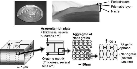
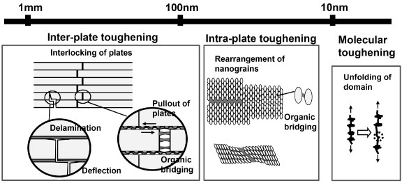
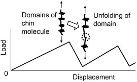
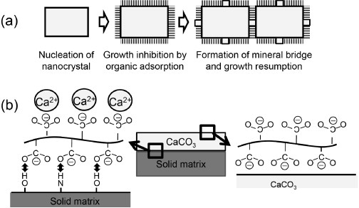
The structure and the toughening mechanism of nacre have been the subject of intensive research over the last 30 years. This interest originates from nacre's excellent combination of strength, stiffness and toughness, despite its high, for a biological material, volume fraction of inorganic phase, typically 95%. Owing to the improvement of nanoscale measurement and observation techniques, significant progress has been made during the last decade in understanding the mechanical properties of nacre. The structure, microscopic deformation behavior and toughening mechanism on the order of nanometers have been investigated, and the importance of hierarchical structure in nacre has been recognized. This research has led to the fabrication of multilayer composites and films inspired by nacre with a layer thickness below 1 μm. Some of these materials reproduce the inorganic/organic interaction and hierarchical structure beyond mere morphology mimicking. In the first part of this review, we focus on the hierarchical architecture, macroscopic and microscopic deformation and fracture behavior, as well as toughening mechanisms in nacre. Then we summarize recent progress in the fabrication of materials inspired by nacre taking into consideration its mechanical properties.

Keywords: composites; mechanical properties; multilayers; nacre; toughening mechanism.


Figures

Figure 1.
Figure 1.
Photographs of the abalone H. gigantea: bottom view (top left) and cross-section (top right) showing nacre at the inner surface. The bottom row presents a schematic diagram of the nacre structure, sequentially magnified from left to right. It shows the ‘brick and mortar’ cross-sectional structure of nacre, consisting of horizontal layers of polygonal aragonite plates within a matrix of organic polymers. Single plates are uniformly aligned vertically in the c-axis [001] direction, and are approximately 5 μm wide and 500 nm thick. The platelet consists of ‘nanograins’, aragonite particles of the order of several tens of nanometers and the organic phase surrounding the nanograins.
Figure 2.
Figure 2.
Illustration of the growth surface of columnar nacre. Amorphous CaCO3 precursor is sequentially deposited as layers of aragonite platelets to form nacre.
Figure 3.
Figure 3.
Cross-section showing the different growth layers in an abalone shell. A schematic diagram is superimposed onto an optical micrograph (left) and the schematic layers have been magnified for clarity. SEM images of the different growth layers (right).
Figure 4.
Figure 4.
(a) Stress–strain curves measured in a tensile test of dried and hydrated nacre. The insets illustrate the deformation behavior during loading. (b) Deformation behavior in the ‘work-hardening’ stage in the stress–strain curve (SEM image). Platelets are progressively pulled out in an accumulative manner. (c) SEM image of the fracture surface after tensile testing. Fracture occurs at the boundaries of a platelet as a result of pull-out.
Figure 5.
Figure 5.
Three models of the origin of interface sliding resistance: (a) the mineral bridging model, (b) the nanoasperity model and (c) the surface waviness model.
Figure 6.
Figure 6.
Hierarchical toughening mechanism of nacre. Toughening can be classified according to the operating dimension, from an inter-platelet mechanism operating at the submicrometer scale, to an intra-platelet mechanism of the order of several tens of nanometers, down to individual organic molecules (nm scale).
Figure 7.
Figure 7.
The formation of a damage zone in front of the notch tip in the tensile fracture test.
Figure 8.
Figure 8.
Schematic diagram of the deformation behavior of proteins with modular structures.
Figure 9.
Figure 9.
In situ deformation of organic matrix between platelets in nacre. (a) Schematic diagram showing the top view of nacre platelets as they separate and the deformation of the matrix between the interfaces. (b) TEM video still image sequence showing matrix ligament bridging between platelets and the subsequent deformation, failure and recoiling of the ligaments (adapted with permission from [91] © 2008 Cambridge University Press).
Figure 10.
Figure 10.
TEM images of nacre platelet cross-sections prepared using ultramicrotomy. (a) A crack through platelets (numbered 1–3) and columnar structures approximately 50 nm across within the platelets are observed. Regions marked b and c are magnified in the right images. (b) White arrows indicate ligaments of organic matrix stretched between the columns. (c) Crack deflection around a nanoparticle within a column (arrow) (adapted with permission from [97] © 2008 Cambridge University Press).
Figure 11.
Figure 11.
(a) Schematic diagram of sequential growth to the oriented structure via a mineral bridge. A nanocrystal is nucleated, and its growth is inhibited because of the adsorption of polymers. The growth restarts by the formation of a mineral bridge, leading to the growth of the adjacent nanocrystals. Thus the nanoscale-orientated architecture continues from nanocrystal to nanocrystal, resulting in an architecture with a specific macroscopic shape. (b) The formation of submicron-thick film is illustrated as follows: (1) acidic macromolecules are adsorbed onto the surface of the solid matrix due to the interaction of the carboxyl group of the acidic macromolecule and the hydroxy group or amino group of the matrix, (2) the macromolecule binds Ca2+ and causes local concentration of Ca2+ on the surface and nucleation of CaCO3, (3) the acidic macromolecules are adsorbed on the growing CaCO3 and inhibit growth in the thickness direction [108, 109].
Figure 12.
Figure 12.
(a) Cross-sections of residual impressions formed by spherical indentation at 300 mN. (b) Magnified view of the central region in (a), showing details of the deformation behavior. (c) Cross-sectional TEM images taken from the bent site of a residual impression, revealing the movement of columnar grains along the intercolumnar boundaries. (d) Schematic diagram of the microscopic mechanism, showing the distortion in the alignment of the columnar grains and columnar unit movement in the form of reorientation/relocation via sliding along intercolumnar boundaries (adapted with permission from [122] © 2009 Cambridge University Press).

References

    1. Mayer G. Science. 2005;310:1144. doi: 10.1126/science.1116994. - DOI - PubMed
    1. Sarikaya M, Tamerler C, Jen A K Y, Schulten K. and Baneyx F. Nat. Mater. 2003;2:577. doi: 10.1038/nmat964. - DOI - PubMed
    1. Meyers M A, Chen P-Y, Lin A Y-M. and Seki Y. Prog. Mater. Sci. 2008;53:1. doi: 10.1016/j.pmatsci.2007.05.002. - DOI
    1. Weiner S. and Addadi L. J. Mater. Chem. 1997;7:689. doi: 10.1039/a604512j. - DOI
    1. Jackson A P, Vincent J F V. and Turner R M. Proc. R. Soc. 1988;234(B):415. doi: 10.1098/rspb.1988.0056. - DOI

LinkOut - more resources