

Multifunctional non-woven fabrics of interfused graphene fibres
- PMID: 27901022
- PMCID: PMC5141476
- DOI: 10.1038/ncomms13684
Multifunctional non-woven fabrics of interfused graphene fibres
Abstract
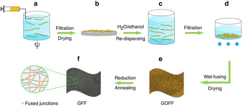
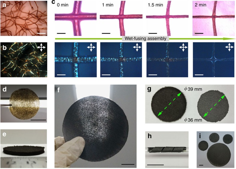
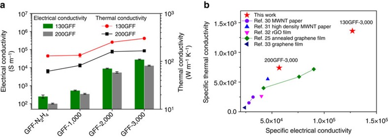
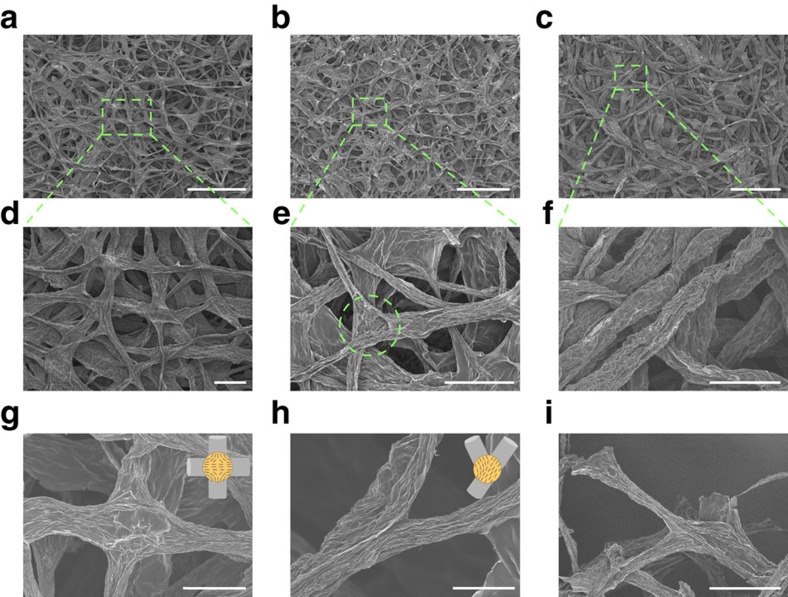
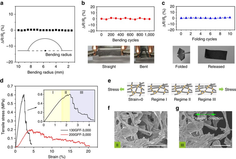
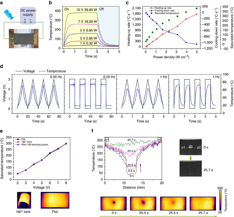
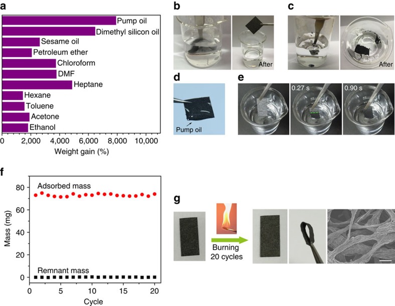
Carbon-based fibres hold promise for preparing multifunctional fabrics with electrical conductivity, thermal conductivity, permeability, flexibility and lightweight. However, these fabrics are of limited performance mainly because of the weak interaction between fibres. Here we report non-woven graphene fibre fabrics composed of randomly oriented and interfused graphene fibres with strong interfibre bonding. The all-graphene fabrics obtained through a wet-fusing assembly approach are porous and lightweight, showing high in-plane electrical conductivity up to ∼2.8 × 10⁴ S m-1 and prominent thermal conductivity of ∼301.5 W m-1 K-1. Given the low density (0.22 g cm-3), their specific electrical and thermal conductivities set new records for carbon-based papers/fabrics and even surpass those of individual graphene fibres. The as-prepared fabrics are further used as ultrafast responding electrothermal heaters and durable oil-adsorbing felts, demonstrating their great potential as high-performance and multifunctional fabrics in real-world applications.
Figures
Similar articles
-
Planar Porous Graphene Woven Fabric/Epoxy Composites with Exceptional Electrical, Mechanical Properties, and Fracture Toughness.ACS Appl Mater Interfaces. 2015 Sep 30;7(38):21455-64. doi: 10.1021/acsami.5b06476. Epub 2015 Sep 15. ACS Appl Mater Interfaces. 2015. PMID: 26331902
-
Flexible Graphene Nanocomposites with Simultaneous Highly Anisotropic Thermal and Electrical Conductivities Prepared by Engineered Graphene with Flat Morphology.ACS Nano. 2020 Sep 22;14(9):11733-11742. doi: 10.1021/acsnano.0c04456. Epub 2020 Sep 4. ACS Nano. 2020. PMID: 32865991
-
A Facile Approach of Fabricating Electrically Conductive Knitted Fabrics Using Graphene Oxide and Textile-Based Waste Material.Polymers (Basel). 2021 Sep 4;13(17):3003. doi: 10.3390/polym13173003. Polymers (Basel). 2021. PMID: 34503044 Free PMC article.
-
Macroscopic, freestanding, and tubular graphene architectures fabricated via thermal annealing.ACS Nano. 2015 Mar 24;9(3):3206-14. doi: 10.1021/acsnano.5b00292. Epub 2015 Mar 9. ACS Nano. 2015. PMID: 25738973
-
A review on strategies for the fabrication of graphene fibres with graphene oxide.RSC Adv. 2020 Feb 5;10(10):5722-5733. doi: 10.1039/c9ra10823h. eCollection 2020 Feb 4. RSC Adv. 2020. PMID: 35497453 Free PMC article. Review.
Cited by
-
Comparative metabolomics reveal the biochemical basis of mulberry fruit decay during low temperature storage.Food Chem X. 2025 May 23;28:102568. doi: 10.1016/j.fochx.2025.102568. eCollection 2025 May. Food Chem X. 2025. PMID: 40511333 Free PMC article.
-
Soft, breathable, and recyclable MXene fabrics for wearable electrophysiological recordings.Mater Horiz. 2025 Jul 22. doi: 10.1039/d5mh00831j. Online ahead of print. Mater Horiz. 2025. PMID: 40694318 Free PMC article.
-
Graphene Modified Multifunctional Personal Protective Clothing.Adv Mater Interfaces. 2019 Nov 8;6(21):1900622. doi: 10.1002/admi.201900622. Epub 2019 Aug 20. Adv Mater Interfaces. 2019. PMID: 32313805 Free PMC article. Review.
-
Surface-Roughened Graphene Oxide Microfibers Enhance Electrochemical Reversibility.Langmuir. 2024 Jun 11;40(23):12124-12136. doi: 10.1021/acs.langmuir.4c01004. Epub 2024 May 30. Langmuir. 2024. PMID: 38815131 Free PMC article.
-
Precise Thermoplastic Processing of Graphene Oxide Layered Solid by Polymer Intercalation.Nanomicro Lett. 2021 Dec 4;14(1):12. doi: 10.1007/s40820-021-00755-8. Nanomicro Lett. 2021. PMID: 34862936 Free PMC article.
References
-
- Xu Z. & Gao C. Graphene in macroscopic order: liquid crystals and wet-spun fibers. Acc. Chem. Res. 47, 1267–1276 (2014). - PubMed
-
- Xu Z. & Gao C. Graphene fiber: a new trend in carbon fibers. Mater. Today 18, 480–492 (2015).
-
- Li Z., Liu Z., Sun H. & Gao C. Superstructured assembly of nanocarbons: fullerenes, nanotubes, and graphene. Chem. Rev. 115, 7046–7117 (2015). - PubMed
-
- Meng F. et al.. Graphene-based fibers: a review. Adv. Mater. 27, 5113–5131 (2015). - PubMed
-
- Jalili R. et al.. Scalable one-step wet-spinning of graphene fibers and yarns from liquid crystalline dispersions of graphene oxide: towards multifunctional textiles. Adv. Funct. Mater. 23, 5345–5354 (2013).
Publication types
LinkOut - more resources
Full Text Sources
Other Literature Sources
