. 2016 Nov 30;16(12):2029.
doi: 10.3390/s16122029.

Uniformly Porous Nanocrystalline CaMgFe1.33Ti₃O12 Ceramic Derived Electro-Ceramic Nanocomposite for Impedance Type Humidity Sensor

Affiliations

Uniformly Porous Nanocrystalline CaMgFe1.33Ti₃O12 Ceramic Derived Electro-Ceramic Nanocomposite for Impedance Type Humidity Sensor

Ashis Tripathy et al. Sensors (Basel). .

Abstract

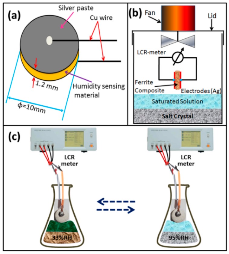
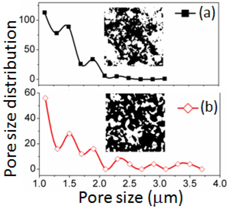
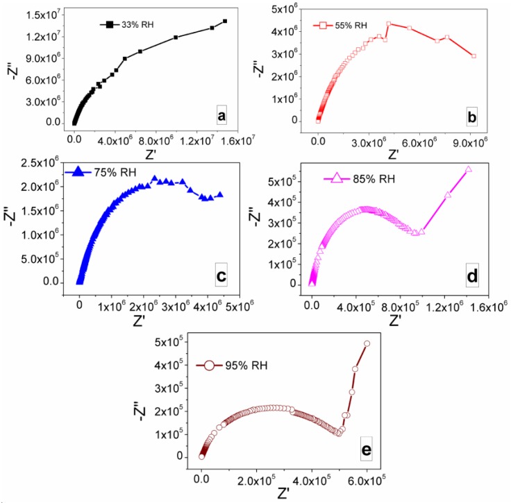
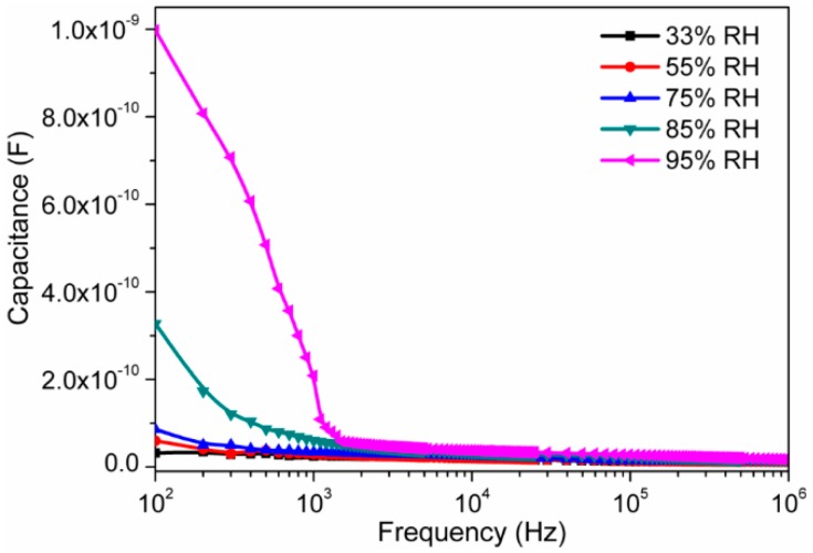
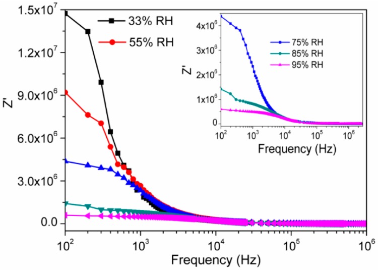
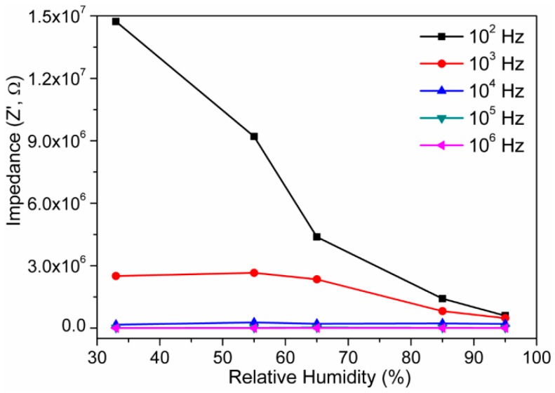
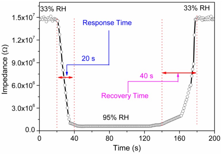
Since humidity sensors have been widely used in many sectors, a suitable humidity sensing material with improved sensitivity, faster response and recovery times, better stability and low hysteresis is necessary to be developed. Here, we fabricate a uniformly porous humidity sensor using Ca, Ti substituted Mg ferrites with chemical formula of CaMgFe1.33Ti₃O12 as humidity sensing materials by solid-sate step-sintering technique. This synthesis technique is useful to control the grain size with increased porosity to enhance the hydrophilic characteristics of the CaMgFe1.33Ti₃O12 nanoceramic based sintered electro-ceramic nanocomposites. The highest porosity, lowest density and excellent surface-hydrophilicity properties were obtained at 1050 °C sintered ceramic. The performance of this impedance type humidity sensor was evaluated by electrical characterizations using alternating current (AC) in the 33%-95% relative humidity (RH) range at 25 °C. Compared with existing conventional resistive humidity sensors, the present sintered electro-ceramic nanocomposite based humidity sensor showed faster response time (20 s) and recovery time (40 s). This newly developed sensor showed extremely high sensitivity (%S) and small hysteresis of <3.4%. Long-term stability of the sensor had been determined by testing for 30 consecutive days. Therefore, the high performance sensing behavior of the present electro-ceramic nanocomposites would be suitable for a potential use in advanced humidity sensors.

Keywords: long-term stability; mechanism; moisture; nanoceramic; porosity; recovery; resistive; sensitivity.


Conflict of interest statement

The authors declare no conflict of interest.

Figures

Figure 1
Figure 1
Schematics of: (a) ceramic pellet with silver electrodes; (b) experimental setup for relative humidity (RH) sensing measurement; and (c) humidity sensitive capacitive device at different RHs.
Figure 2
Figure 2
X-ray diffraction (XRD) patterns of: (a) unsintered; and (b) sintered (at 1050 °C) CaMgFe1.33Ti3O12 nanoceramic composites. X-ray source was Cu-Kα radiation, and 2θ was 20°–50°. Note: the different colored planes represent the crystalline planes of respective materials: pink, Fe2O3; black, TiO2; dark red, MgCO3; green, CaCO3; purple, CaO; red, Fe2MgTi3O10; blue, CaTiO3; and brown, Fe3O4.
Figure 3
Figure 3
Scanning electron micrographs of the specimens for: (a) unsintered; and (b) sintered at 1050 °C. Note: the green and yellow arrows indicate pores and particles; and vertical red and horizontal blue arrows indicate the armalcolite (average size: 685 nm) and perovskite (<100 nm) structure phases, respectively. The grain and grain boundary are also clearly revealed at the large size armalcolite phase.
Figure 4
Figure 4
Pore size distribution (PSD) plots of: (a) unsintered; and (b) sintered (at 1050 °C) materials quantifying from the respective Inverted SEM figures using ImageJ. The corresponding Inverted SEM image is also presented as Inset image for both the materials. The black analyzed areas in the Insets indicate pores and white areas represent the particles.
Figure 5
Figure 5
Nyquist plots of sintered electro-ceramic nanocomposite device at: (a) 33% RH; (b) 55% RH; (c) 75% RH; (d) 85% RH; and (e) 97% RH. Note: At lower RH (33%, 55% and 75% RH) (ac) the semicircles are formed and the curvature of the semicircle decreases with increasing RH, as a result the value of intrinsic impedance decreases, which is mainly due to the interaction between the sensing material and water particles. With elevating of RH from 85% to 95%, a linear curve appeared in the low-frequency range and the semicircle became smaller (d,e). The ionic and/or electrolytic conductivity played crucial role in the formation of straight line in case of complex impedance plot.
Figure 6
Figure 6
Variation of capacitance of electro-ceramic nanocomposite at different relative humidity as a function of frequency in logarithmic scale at 25 °C. Note the increase in capacitance value with increasing of RH and at higher humidity range (>85% RH), a sharp decreased response of capacitance with frequency.
Figure 7
Figure 7
Variation of real impedance (Z′) of electro-ceramic nanocomposite at different relative humidity as a function of frequency in logarithmic scale at 25 °C. Note: As humidity increases, the value of impedance decreases and the decreased rate is fast in the lower frequency range and it becomes slower at higher frequencies (>104 Hz) (inset: Magnified Z′ vs. log(f) response at 75%, 85% and 97% RH).
Figure 8
Figure 8
Variation of imaginary (Z″) impedance of electro-ceramic nanocomposite at different relative humidity as a function of frequency in logarithmic scale at 25 °C. Inset image represents a magnified scale of Z″ vs. log(f) plot of developed ceramic at higher RH (at 75%, 85% and 95% RH) with prominent relaxation peak. Note: Lower frequency relaxation peaks are observed and these peaks are more prominent at higher RH (>75% RH).
Figure 9
Figure 9
Impedance versus RH measured of electro-ceramic nanocomposite at various frequencies at 25 °C. Note: the impedance varies from 1.47 × 10⁷ Ω to 6 × 10⁵ Ω; since highest sensitivity of 0.23 MΩ/Δ% RH was found at 102 Hz frequency, 102 Hz was considered as most suitable test frequency in our further analyses.
Figure 10
Figure 10
Response and recovery curve of electro-ceramic nanocomposite measured at 102 Hz for humidity levels between 33% RH and 95% RH at 102 Hz. Note: Response time is ~20 s and Recovery time is ~40 s.
Figure 11
Figure 11
Humidity response of the sensor based on sintered electro-ceramic nanocomposite during humidification and desiccation process at 102 Hz. Note: The hysteresis loss value is extremely low (~3.4%) owing to the faster rate of adsorption and desorption of water particles on the electro-ceramic surface. This hysteresis was significantly lower than other conventional sensors.
Figure 12
Figure 12
Long term stability property of the sensor based on sintered electro-ceramic nanocomposite over 30 days of measurements at 102 Hz and 1 V. Note: Stability of the sensors was tested via by examining the humidity-resistivity properties at 25 °C, in the humidity range of 33%–95% RH over 30 days in a regular interval of each two days; here, no significant change was found.
Figure 13
Figure 13
A schematic humidity sensing mechanism of the sensor based on CaMgFe1.33Ti3O12 nanoceramic derived sintered electro-ceramic armalcolite nanocomposite at low and high humidity. Note: The water molecular adsorption on sintered electro-ceramic nanocomposite: in 1st layer, the water molecules were attached to the electro-ceramic via two hydrogen bonds, whereas, in the 2nd layer, they were adsorbed only via one hydrogen bond.
Figure 14
Figure 14
The variation of real (M′) modulus components of the electro-ceramic nanocomposite at different RH as a function of frequency in logarithmic scale at 25 °C. Note: A sigmoidal shape curve is observed, when the value of M′ changes from low to high RH value. This is mainly due to the existence of relaxation phenomena inside the newly developed electro-ceramic nanocomposite sensor at the time of interaction to the water particles.
Figure 15
Figure 15
Variations in imaginary (M") modulus components of the sensor based on electro-ceramic nanocomposite at different RH as a function of frequency in logarithmic scale at 25 °C. Note: The relaxation peak frequencies are shifted in the direction of higher frequencies as the relative humidity increased. The shifting of peaks towards higher frequencies is a clear indication of an increase in direct current (DC) conductivity with relative humidity.
Figure 16
Figure 16
Complex modulus responses between real (M′) and imaginary (M″) at different RH of the sensor based on sintered electro-ceramic nanocomposite at 25 °C. Note: The radius of the semicircle decreases, with increased relative humidity, which suggests that the bulk resistance of the electro-ceramic nanocomposite humidity sensing device decreases with the increase in RH.

References

    1. Chen Z., Lu C. Humidity sensors: A review of materials and mechanisms. Sens. Lett. 2005;3:274–295. doi: 10.1166/sl.2005.045. - DOI
    1. Comini E., Sberveglieri G. Metal oxide nanowires as chemical sensors. Mater. Today. 2010;13:36–44. doi: 10.1016/S1369-7021(10)70126-7. - DOI - PubMed
    1. Kong J., Franklin N.R., Zhou C., Chapline M.G., Peng S., Cho K., Dai H. Nanotube molecular wires as chemical sensors. Science. 2000;287:622–625. doi: 10.1126/science.287.5453.622. - DOI - PubMed
    1. Hsueh H., Hsueh T., Chang S., Hung F., Weng W., Hsu C., Dai B. Si nanowire-based humidity sensors prepared on glass substrate. IEEE Sens. J. 2011;11:3036–3041. doi: 10.1109/JSEN.2011.2156781. - DOI
    1. Huang J., Virji S., Weiller B.H., Kaner R.B. Polyaniline nanofibers: Facile synthesis and chemical sensors. J. Am. Chem. Soc. 2003;125:314–315. doi: 10.1021/ja028371y. - DOI - PubMed

LinkOut - more resources