Review
. 2017 Jan 15:109:26-44.
doi: 10.1016/j.addr.2016.11.006. Epub 2016 Dec 3.

Proton therapy - Present and future

Affiliations
Review

Proton therapy - Present and future

Radhe Mohan et al. Adv Drug Deliv Rev. .

Abstract

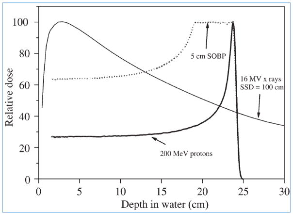
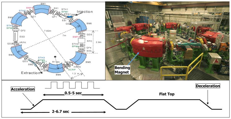
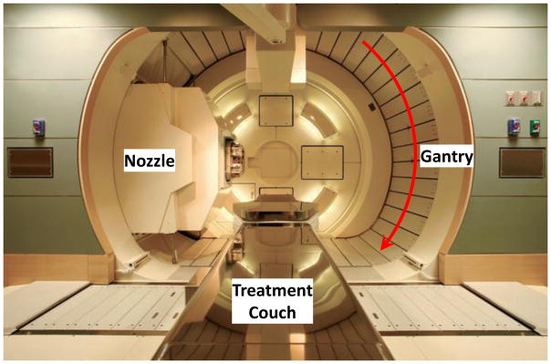
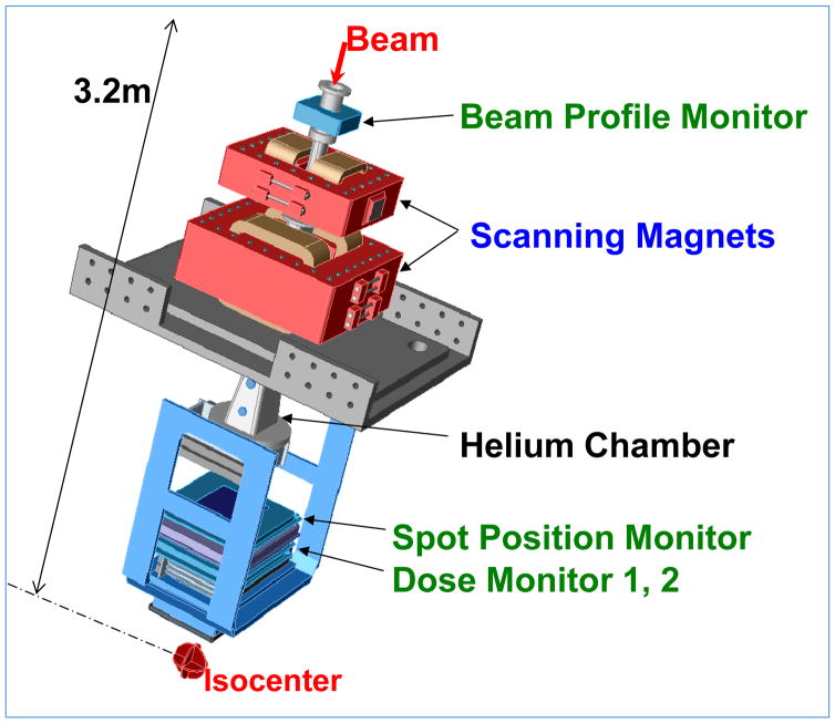
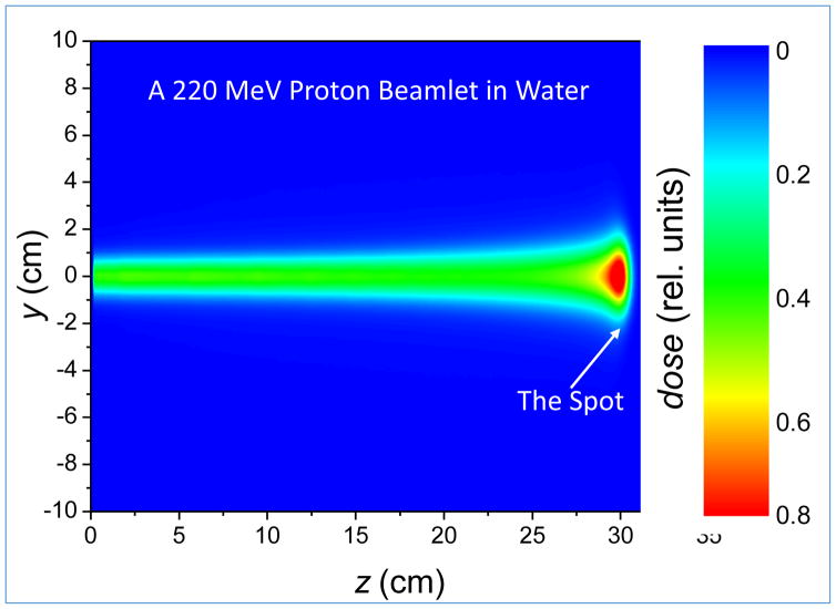
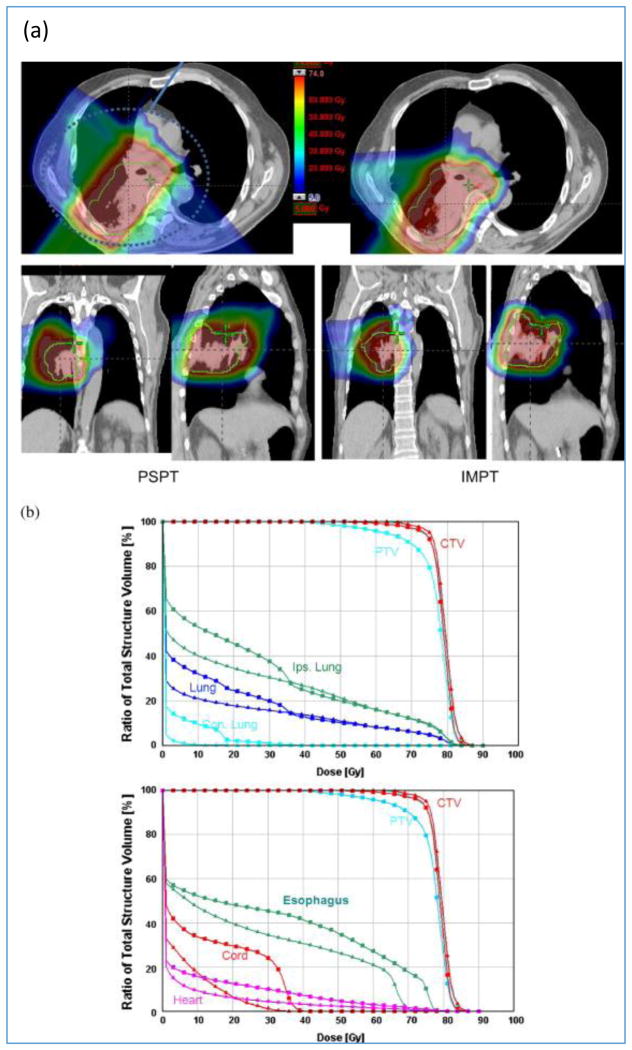
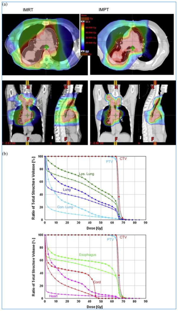
In principle, proton therapy offers a substantial clinical advantage over conventional photon therapy. This is because of the unique depth-dose characteristics of protons, which can be exploited to achieve significant reductions in normal tissue doses proximal and distal to the target volume. These may, in turn, allow escalation of tumor doses and greater sparing of normal tissues, thus potentially improving local control and survival while at the same time reducing toxicity and improving quality of life. Protons, accelerated to therapeutic energies ranging from 70 to 250MeV, typically with a cyclotron or a synchrotron, are transported to the treatment room where they enter the treatment head mounted on a rotating gantry. The initial thin beams of protons are spread laterally and longitudinally and shaped appropriately to deliver treatments. Spreading and shaping can be achieved by electro-mechanical means to treat the patients with "passively-scattered proton therapy" (PSPT) or using magnetic scanning of thin "beamlets" of protons of a sequence of initial energies. The latter technique can be used to treat patients with optimized intensity modulated proton therapy (IMPT), the most powerful proton modality. Despite the high potential of proton therapy, the clinical evidence supporting the broad use of protons is mixed. It is generally acknowledged that proton therapy is safe, effective and recommended for many types of pediatric cancers, ocular melanomas, chordomas and chondrosarcomas. Although promising results have been and continue to be reported for many other types of cancers, they are based on small studies. Considering the high cost of establishing and operating proton therapy centers, questions have been raised about their cost effectiveness. General consensus is that there is a need to conduct randomized trials and/or collect outcomes data in multi-institutional registries to unequivocally demonstrate the advantage of protons. Treatment planning and plan evaluation of PSPT and IMPT require special considerations compared to the processes used for photon treatment planning. The differences in techniques arise from the unique physical properties of protons but are also necessary because of the greater vulnerability of protons to uncertainties, especially from inter- and intra-fractional variations in anatomy. These factors must be considered in designing as well as evaluating treatment plans. In addition to anatomy variations, other sources of uncertainty in dose delivered to the patient include the approximations and assumptions of models used for computing dose distributions for planning of treatments. Furthermore, the relative biological effectiveness (RBE) of protons is simplistically assumed to have a constant value of 1.1. In reality, the RBE is variable and a complex function of the energy of protons, dose per fraction, tissue and cell type, end point, etc. These uncertainties, approximations and current technological limitations of proton therapy may limit the achievement of its true potential. Ongoing research is aimed at better understanding the consequences of the various uncertainties on proton therapy and reducing the uncertainties through image-guidance, adaptive radiotherapy, further study of biological properties of protons and the development of novel dose computation and optimization methods. However, residual uncertainties will remain in spite of the best efforts. To increase the resilience of dose distributions in the face of uncertainties and improve our confidence in dose distributions seen on treatment plans, robust optimization techniques are being developed and implemented. We assert that, with such research, proton therapy will be a commonly applied radiotherapy modality for most types of solid cancers in the near future.

Keywords: Intensity-modulated proton therapy; Particle therapy; Proton therapy; Radiation therapy.


Figures

Figure 1
Figure 1
Depth-dose curves for a 200 MeV proton beam: both unmodulated and with a 5 cm spread-out Bragg peak (SOBP), compared with a 16 MV x-ray beam (for 10 ×10 cm2 fields). The curves are normalized in each case to 100 at maximum dose. (Adapted from Jones, reproduced with permission).[1]
Figure 2
Figure 2
Acceleration of protons in a cyclotron. A fixed magnetic field bends the path of protons, and they are accelerated by a square wave electric field applied between gaps of two D-shaped regions (known as “Dees”). As energy increases, the radius of the proton path increases until the designated maximum is reached and protons are extracted. Panel on the right shows key components of the cyclotrons. (Adapted from [16].)
Figure 3
Figure 3
The synchrotron at MD Anderson Proton Therapy Center. A batch of protons is initially accelerated by a linear accelerator to a low energy (7 MeV) and injected into the synchrotron. Protons, as they are accelerated by the successive application of an alternating electric field, are constrained to move in a fixed circular path by increasing the magnetic field. When the batch of protons has reached the specified energy, it is extracted and transmitted to one of the treatment rooms. (Adapted from [16].)
Figure 4
Figure 4
Nozzle (treatment head) mounted on a rotating gantry to direct the beam to the tumor in the patient lying on the treatment couch.
Figure 5
Figure 5
Layout of the treatment floor of MD Anderson s Proton Therapy Center.
Figure 6
Figure 6
(a) A passive scattering nozzle. The beam entering the nozzle is spread longitudinally by the range modulator wheel (RMW) and spread laterally by two scatterers; one of them is built into the RMW. The inset (b) illustrates how the RMW interposes steps of different thickness to produce Bragg peaks of different ranges and intensities, which combine to create an SOBP shown in panel (c). The proton beam is turned on at the thinnest step. The width of the Bragg peak can be changed by gating the beam off at an appropriate step. Panels (d) and (e) show a brass aperture and a compensator respectively.
Figure 7
Figure 7
A Scanning beam nozzle (Hitachi at MDACC). The thin beamlets of a sequence of energies entering the nozzle are spread laterally by a pair of x- and y-magnets to create a three-dimensional pattern of dose distribution. Magnet strengths are adjusted to confine the Bragg peaks of beamlets (“spots”) to within the target volume. Intensities of beamlets, computed using a treatment planning system, are optimized in order to conform the high and uniform dose pattern to the target volume and appropriately spare critical normal tissues. Various monitoring systems ensure that the characteristics of the proton beam are within specifications and that the requisite dose is accurately delivered. Part of the path from the beamlet entry position to the isocenter is replaced with a helium chamber to reduce lateral dispersion of the scanning beamlet in air.
Figure 8
Figure 8
Monoenergetic 222 MeV beamlet with FWHM of ~13 mm at the entrance to the water phantom and ~30 mm at the Bragg peak.
Figure 9
Figure 9
Compensator smearing. Panel (a) shows a compensator designed assuming perfect alignment. Panel (b) shows a smeared (expanded) compensator to account for misalignment of the compensator with anatomy and anatomic structures relative to each other. The smearing process essentially reduces the width of the higher thickness regions of the compensator, which allows protons to penetrate more deeply even when adjacent higher density tissues move into their path. Smearing may necessitate an increase in the modulation width to ensure that dose to the proximal edge is not compromised. [17]
Figure 10
Figure 10
(a) PSPT vs. IMPT dose distributions. Due to the requirement of sparing of critical normal structures, adequate coverage of the target could be achieved with PSPT but was possible with IMPT. (b) DVHs for the PSPT (squares) and IMPT (triangles) plans are shown. [18]
Figure 11
Figure 11
(a) IMRT vs. IMPT dose distributions. Large dose bath outside the target for IMRT is apparent. (b) DVHs for IMRT (squares) and IMPT (triangles) plans are shown.[18]
Figure 12
Figure 12
Inhomogeneous individual field IMPT target dose distributions (F1, F2, F3, F4) and a homogenous combined dose distribution for a head and neck case. (Adapted from a figure provided by A. Lomax, PSI, private communication.)
Figure 13
Figure 13
(a) shows the impact of the respiratory motion of a lung tumor on the penetration of a proton beam. Figure 13(b) shows that, for a 7-beam IMRT plan, the effect of significant tumor shrinkage after two weeks to treatments is negligible, but it is considerable for a 3-beam passively scattered proton plan (lower panel).
Figure 14
Figure 14
Passively scattered proton therapy dose distributions for a non-small cell lung cancer (NSCLC) patient computed with (a) Monte Carlo simulations and (b) a conventional commercial treatment planning system (TPS). Panel (c) shows the TPS – MC difference dose distribution, illustrating the under-dosing in conventional model predictions. Similarly the difference MC – TPS (not shown) would illustrate regions of over-dosing. (Mirkovic, et al. Unpublished, private communication)
Figure 15
Figure 15
A two-beam IMPT plan for brain tumor optimized based on criteria defined in terms of constant RBE of 1.1 (squares) and in terms of variable RBE computed using a model published by Wilkens, et al. (triangles). After optimization, both dose distributions were converted to variable RBE-weighted dose for comparison. The dose to the gross tumor volume (GTV) is more homogeneous for variable RBE-weighted optimization but lower to normal tissues to varying degrees. Notably, the dose in a 5 mm shell surrounding the GTV is reduced substantially. (Unpublished, Courtesy of Cao, University of Houston.)
Figure 16
Figure 16
Normal lung (i.e., Lung – CTV) dose volume histograms for a NSCLC IMPT plan optimized based on conventional (i.e., PTV-based) criteria. The blue band represents nine different dose distributions. Six of them were obtained by shifting the patient (i.e., the CT image) along +/− x, y and z directions by margins typically assigned for positioning uncertainty. Two more were obtained by scaling the CT numbers so that the range of protons is increased or decreased by the estimated uncertainty in range. The ninth dose distribution is the nominal dose distribution without considering any uncertainty. Its corresponding lung DVH is represented by the dark blue line. During optimization, the volume receiving 20 Gy (RBE) is constrained to within 37% of the total lung volume. The width of the band at 20 Gy (RBE) along the volume axis is a measure of the robustness of this critical dose-volume index for lung. The worst case DVH will be the upper bound of the band. (Adapted from Liu, et al.[64])
Figure 17
Figure 17
An illustrative example comparing DVHs of NSCLC IMPT plans optimized using two different approaches. The conventional approach used the criteria defined based on PTV dose distributions; whereas the robust optimization used the approach described in the text. Afterwards, the robustness of both dose distributions was evaluated using the approach described in section 6.4. The narrower DVH bands resulting from robust optimization demonstrate its benefit. An interesting byproduct of robust optimization is that, in general, it leads to improved homogeneity of target dose and greater sparing of normal tissues. (Adapted from Liu, et al.[64])

References

    1. Jones DTL. Present status and future trends of heavy particle radiotherapy. In: Baron E, Lieuvin M, editors. Cyclotrons and Their Applications 1998. Institute of Physics Publishing; Bristol, UK: 1999. pp. 13–20.
    1. Wilson RR. Radiological use of fast protons. Radiology. 1946;47:487–491. - PubMed
    1. Lawrence JH, Tobias CA, Born JL, Mc CR, Roberts JE, Anger HO, Low-Beer BV, Huggins CB. Pituitary irradiation with high-energy proton beams: a preliminary report. Cancer research. 1958;18:121–134. - PubMed
    1. Suit HD, Goitein M, Tepper J, Koehler AM, Schmidt RA, Schneider R. Explorotory study of proton radiation therapy using large field techniques and fractionated dose schedules. Cancer. 1975;35:1646–1657. - PubMed
    1. Coutrakon G, Hubbard J, Johanning J, Maudsley G, Slaton T, Morton P. A performance study of the Loma Linda proton medical accelerator. Med Phys. 1994;21:1691–1701. - PubMed