

Robust spin-orbit torque and spin-galvanic effect at the Fe/GaAs (001) interface at room temperature
- PMID: 27958265
- PMCID: PMC5159805
- DOI: 10.1038/ncomms13802
Robust spin-orbit torque and spin-galvanic effect at the Fe/GaAs (001) interface at room temperature
Abstract
Interfacial spin-orbit torques (SOTs) enable the manipulation of the magnetization through in-plane charge currents, which has drawn increasing attention for spintronic applications. The search for material systems providing efficient SOTs, has been focused on polycrystalline ferromagnetic metal/non-magnetic metal bilayers. In these systems, currents flowing in the non-magnetic layer generate-due to strong spin-orbit interaction-spin currents via the spin Hall effect and induce a torque at the interface to the ferromagnet. Here we report the observation of robust SOT occuring at a single crystalline Fe/GaAs (001) interface at room temperature. We find that the magnitude of the interfacial SOT, caused by the reduced symmetry at the interface, is comparably strong as in ferromagnetic metal/non-magnetic metal systems. The large spin-orbit fields at the interface also enable spin-to-charge current conversion at the interface, known as spin-galvanic effect. The results suggest that single crystalline Fe/GaAs interfaces may enable efficient electrical magnetization manipulation.
Figures
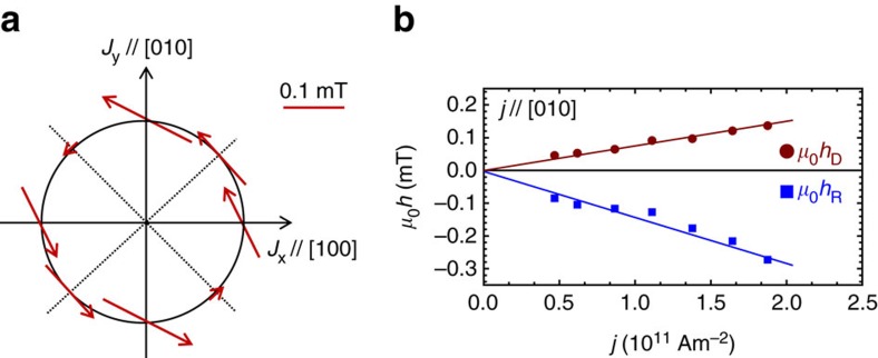
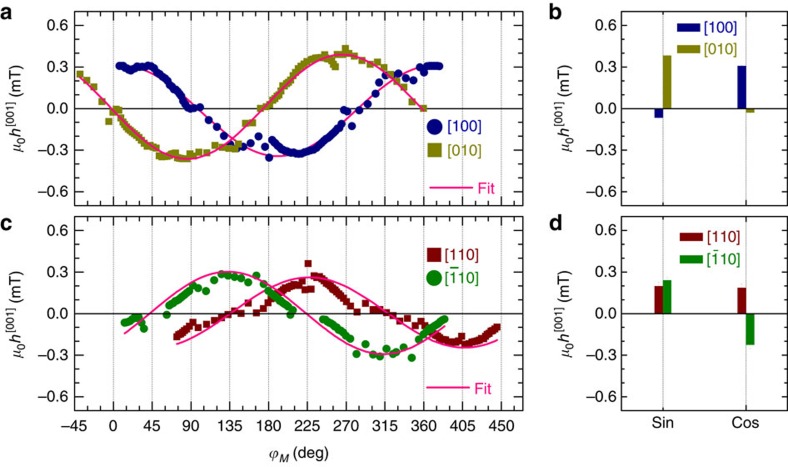
 10] orientated devices. (d) Fitting coefficients of sinϕM and cosϕM. The error bar in b,d is the s.d. obtained from the fit. All the fields are normalized by a unit current density of 1011 Am−2.
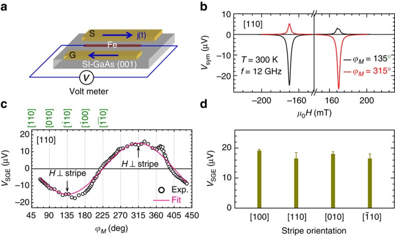
Similar articles
-
Field-Free Spin-Orbit Torque Switching of Perpendicular Magnetization by the Rashba Interface.ACS Appl Mater Interfaces. 2019 Oct 23;11(42):39369-39375. doi: 10.1021/acsami.9b13622. Epub 2019 Oct 11. ACS Appl Mater Interfaces. 2019. PMID: 31603641
-
Harnessing Orbital-to-Spin Conversion of Interfacial Orbital Currents for Efficient Spin-Orbit Torques.Phys Rev Lett. 2020 Oct 23;125(17):177201. doi: 10.1103/PhysRevLett.125.177201. Phys Rev Lett. 2020. PMID: 33156648
-
Electric-Field Control of Spin-Orbit Torques in WS2/Permalloy Bilayers.ACS Appl Mater Interfaces. 2018 Jan 24;10(3):2843-2849. doi: 10.1021/acsami.7b16919. Epub 2018 Jan 11. ACS Appl Mater Interfaces. 2018. PMID: 29297228
-
Characterization and Manipulation of Spin Orbit Torque in Magnetic Heterostructures.Adv Mater. 2018 Apr;30(17):e1705699. doi: 10.1002/adma.201705699. Epub 2018 Feb 22. Adv Mater. 2018. PMID: 29468735 Review.
-
Current-Induced Spin-Orbit Torques for Spintronic Applications.Adv Mater. 2020 Sep;32(35):e1907148. doi: 10.1002/adma.201907148. Epub 2020 Mar 6. Adv Mater. 2020. PMID: 32141681 Review.
Cited by
-
Absence of Spin-Orbit Torque and Discovery of Anisotropic Planar Nernst Effect in CoFe Single Crystal.Adv Sci (Weinh). 2023 Sep;10(27):e2301409. doi: 10.1002/advs.202301409. Epub 2023 Jul 23. Adv Sci (Weinh). 2023. PMID: 37485640 Free PMC article.
-
Signatures of magnetism control by flow of angular momentum.Nature. 2024 Sep;633(8030):548-553. doi: 10.1038/s41586-024-07914-y. Epub 2024 Sep 4. Nature. 2024. PMID: 39232172 Free PMC article.
-
Prospect of Spin-Orbitronic Devices and Their Applications.iScience. 2020 Sep 28;23(10):101614. doi: 10.1016/j.isci.2020.101614. eCollection 2020 Oct 23. iScience. 2020. PMID: 33089103 Free PMC article. Review.
-
Electric Field Control of Spin-Orbit Torque Magnetization Switching in a Spin-Orbit Ferromagnet Single Layer.Adv Sci (Weinh). 2023 Aug;10(24):e2301540. doi: 10.1002/advs.202301540. Epub 2023 Jun 17. Adv Sci (Weinh). 2023. PMID: 37329321 Free PMC article.
-
Spin homojunction with high interfacial transparency for efficient spin-charge conversion.Sci Adv. 2022 Sep 23;8(38):eabq2742. doi: 10.1126/sciadv.abq2742. Epub 2022 Sep 21. Sci Adv. 2022. PMID: 36129983 Free PMC article.
References
-
- Dresselhaus G. Spin-orbit coupling effects in zincblende structures. Phys. Rev. 100, 580–586 (1955).
-
- Bychkov Y. A. & Rashba E. I. Oscillatory effects and the magnetic susceptibility of carriers in inversion layers. J. Phys. C: Solid State Phys. 17, 6039–6045 (1984).
-
- Aronov A. G., Lyanda-Geller Y. B. & Pikus G. E. Spin polarization of electrons by an electric current. Sov. Phys. JETP 73, 537–541 (1991).
-
- Edelstein V. M. Spin polarization of conduction electrons induced by electric current in two-dimentional asymmetric electron systems. Solid State Commun. 73, 233–235 (1990).
-
- Sinova J. et al.. Universal intrinsic spin Hall effect. Phys. Rev. Lett. 92, 126603 (2004). - PubMed
Publication types
LinkOut - more resources
Full Text Sources
Other Literature Sources
Molecular Biology Databases
