Review
. 2016 Dec 5:2:28.
doi: 10.1186/s40942-016-0052-9. eCollection 2016.

Vitreoretinal instruments: vitrectomy cutters, endoillumination and wide-angle viewing systems

Affiliations
Review

Vitreoretinal instruments: vitrectomy cutters, endoillumination and wide-angle viewing systems

Paulo Ricardo Chaves de Oliveira et al. Int J Retina Vitreous. .

Abstract

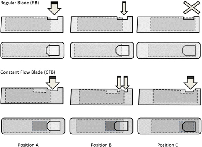
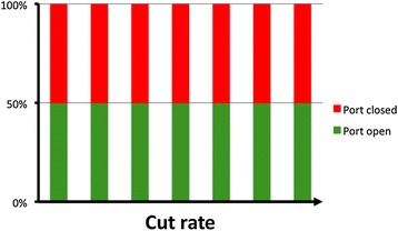
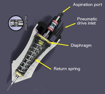
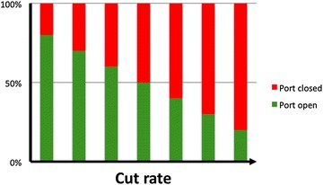
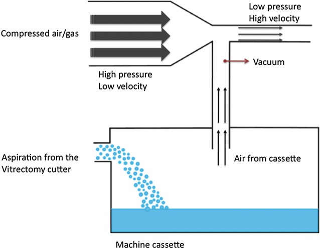
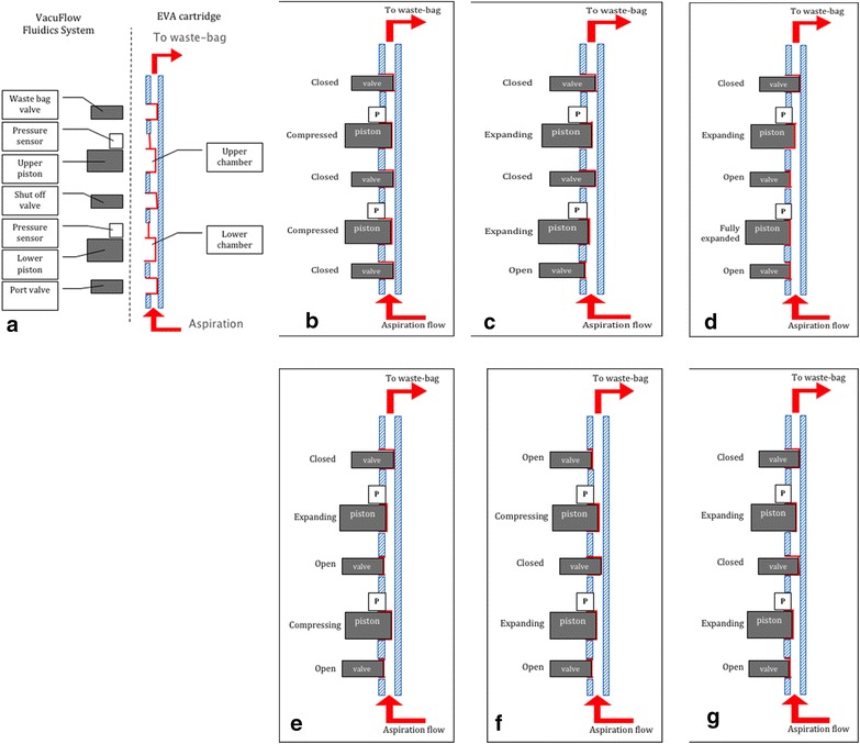
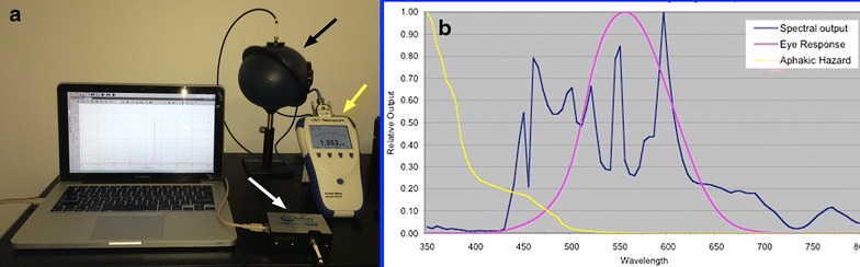
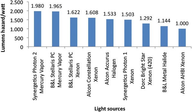
There have been many advances in vitreoretinal surgery since Machemer introduced the concept of pars plana vitrectomy, in 1971. Of particular interest are the changes in the vitrectomy cutters, their fluidics interaction, the wide-angle viewing systems and the evolution of endoillumination through the past decade and notably in the last few years. The indications of 27-gauge surgery have expanded, including more complex cases. Cut rates of up to 16,000 cuts per minute are already available. New probe designs and pump technology have allowed duty cycle performances of near 100% and improved flow control. The smaller vitrectomy diameter can be positioned between narrow spaces, allowing membrane dissection and serving as a multifunctional instrument. Enhanced endoillumination safety can be achieved by changing the light source, adding light filters, increasing the working distance and understanding the potential interactions between light and vital dyes commonly used to stain the retina. Wide-angle viewing systems (contact, non-contact or a combination of both) provide a panoramic view of the retina. Non-contact systems are assistant-independent, while contact systems may be associated with better image resolution. This review will cover some current aspects on vitrectomy procedures, mainly assessing vitrectomy cutters, as well as the importance of endoillumination and the use of wide-angle viewing systems.

Keywords: Endoillumination; Vitrectomy cutters; Wide-angle viewing systems.


Figures

Fig. 1
Fig. 1
Flow rate of a pure/aqueous fluid according to the “Poiseuille’s law”; ∆P is the pressure difference across the length of the probe needle, r is the inner radius of the vitrectomy probe, η is the viscosity of the fluid and L corresponds to the length of the vitrectomy tube
Fig. 2
Fig. 2
Comparison of the regular guillotine-shaped and the constant flow blade (CFB). The regular guillotine-shaped blade (upper portion) completely closes on position C, whereas the CFB maintains the same amount of port opening during the total cutting cycle, while chopping the vitreous at the proximal and distal edge of the blade (position C—lower portion). Image courtesy and reproduced with permission of Dr. Tomasso Rossi. First available on Rossi et al. [32]
Fig. 3
Fig. 3
Duty cycle of a typical eletric cutter, with a 50% value (the port is open approximately 50% of the whole cutting cycle) up to the maximum cut speed set up on the machine
Fig. 4
Fig. 4
Pneumatic spring return driven vitrectomy probe. An air pulse pushes down the diaphragm located inside the vitrectomy probe, leading the port to a closed position (the guillotine movement); at the same time, a spring is compressed and forces the diaphragm back to the open port position. Image provided by Alcon, USA
Fig. 5
Fig. 5
Time of port open and port closed of a typical pneumatic spring return cutter. As cut speed increases the duty cycle decreases to some degree
Fig. 6
Fig. 6
Dual pneumatic vitrectomy cutter. An air pulse pushes down the diaphragm located inside the vitrectomy probe, leading the port to a closed position (the guillotine movement); another air pulse, in a separate air line, pushes the diaphragm back to the port open position. Image courtesy of Alcon (Ultravit® probe—Alcon, USA)
Fig. 7
Fig. 7
Duty cycle (DC) pattern of 23 gauge (a) and 25+ gauge (b) dual pneumatic cutters according to the cut rate. As cut rate increases there is a trend to a 50% DC, regardless of the initial selected mode (50/50, shave mode or core mode). Source: Alcon data on file/Test Report 954-2020-003
Fig. 8
Fig. 8
Basic saline solution (BSS) aspiration flow rate pattern of three different 27-gauge vitrectomy cutters according to the cut rate. The two-dimensional cutter (TDC; DORC International) shows consistency of the flow rate irrespective of the cut rate, illustrating the approximately 100% duty cycle mechanism of new vitrectomy cutter designs. Figure courtesy of DORC International
Fig. 9
Fig. 9
Peristaltic pump. The fluid within a tube is compressed and forced to dislocate by the roller. A gradient of pressure is created between the infusion and the point of pressure, leading to aspiration and directly controlling flow by the roller rotational speed
Fig. 10
Fig. 10
Venturi pump. Vacuum is generated by a flow of air/gas and is transmitted into the cassette. The air inside the cassette is aspirated and flow from the cutter aspiration line reaches the cassette, as a result of the created vacuum. The flow is controlled by the vacuum levels
Fig. 11
Fig. 11
Vacuflow VTI (Valve Timing Intelligence). The EVA cartridge contains two small flow chambers (6 ml), which volumes are controlled by computer-based pistons, valves and high-sensitivity pressure sensors located on the EVA platform (a). Sequence: b At the start of the sequence both chambers of the cartridge are compressed and the valves are closed. c When there is a demand to generate aspiration flow the port valve opens and the lower chamber expands. Due to this expansion the fluid will be drawn into the fluid displacement chamber, resulting in aspiration flow. The speed of the expansion determines the amount of aspiration flow: higher speeds will achieve higher flow rates. The associated pressure is measured with the chamber pressure sensor. Meanwhile the fluidics system creates an identical pressure in the upper chamber by expanding the upper chamber and keeps this equal to the pressure of the bottom chamber. d As soon as the lower chamber is fully expanded the shut off valve opens. At this point the pressure in both chambers are identical, eliminating pressure pulsations in the aspiration line. e From this point the lower chamber is being compressed in order to empty the chamber, while the upper chamber is being further expanded. The expansion of the upper chamber is faster than the bottom chamber due to the fact that it must generate aspiration flow and displace the fluid from the lower chamber into the upper chamber. f Once the lower chamber is fully compressed the shut off valve closes and the lower chamber expands to generate the aspiration flow. Meanwhile the waste bag valve opens and the fluid in the top chamber is compressed emptying it into the waste bag. g As soon as the upper chamber is emptied into the waste bag it expands to create a pressure similar to the lower chamber. Once the lower chamber is fully expanded the cycle repeats. Figure courtesy of DORC International
Fig. 12
Fig. 12
a Set up for obtaining the spectral curve and power output of a light source. The spectrophotometer (white arrow) and power meter (yellow arrow) are linked to the integration sphere (black arrow). The light shining into the integration sphere generates a spectral curve captured by the spectrophotometer also linked to the computer software. The power obtained is directly shown by the power meter. b Spectral curve of a light source (blue curve), as a function of wavelength and intensity output, against an aphakic hazard curve (yellow) and a photopic eye response curve (purple)
Fig. 13
Fig. 13
Safety calculations for different commercially available light sources, expressed in lumens hazard/watt (personal data). The higher the lumens necessary to create a watt of hazard, the safer the light source (for comparison, brightness, working distance and cone of illumination were all kept constant between the platforms)
Fig. 14
Fig. 14
Retina threshold time of commercially available light sources according to their working distance from the retina (personal data)

References

    1. Machemer R. The development of pars plana vitrectomy: a personal account. Graefes Arch Clin Exp Ophthalmol. 1995;233(8):453–468. doi: 10.1007/BF00183425. - DOI - PubMed
    1. Machemer R, Buettner H, Norton EW, Parel JM. Vitrectomy: a pars plana approach. Trans Am Acad Ophthalmol Otolaryngol. 1971;75(4):813–820. - PubMed
    1. Charles S. The history of vitrectomy: innovation and evolution. Retina Today. 2008:27–9.
    1. Fujii GY, De Juan E, Jr, Humayun MS, Chang TS, Pieramici DJ, Barnes A, et al. Initial experience using the transconjunctival sutureless vitrectomy system for vitreoretinal surgery. Ophthalmology. 2002;109(10):1814–1820. doi: 10.1016/S0161-6420(02)01119-3. - DOI - PubMed
    1. Fujii GY, De Juan E, Jr, Humayun MS, Pieramici DJ, Chang TS, Awh C, et al. A new 25-gauge instrument system for transconjunctival sutureless vitrectomy surgery. Ophthalmology. 2002;109(10):1807–1812. doi: 10.1016/S0161-6420(02)01179-X. - DOI - PubMed