Review
. 2017 Jan;6(1):10.1002/adhm.201601118.
doi: 10.1002/adhm.201601118. Epub 2016 Dec 20.

3D Bioprinting for Organ Regeneration

Affiliations
Review

3D Bioprinting for Organ Regeneration

Haitao Cui et al. Adv Healthc Mater. 2017 Jan.

Abstract

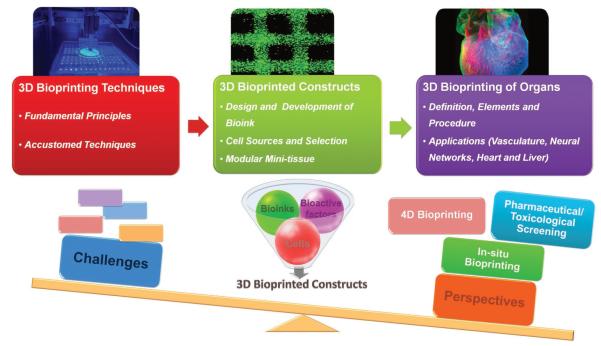
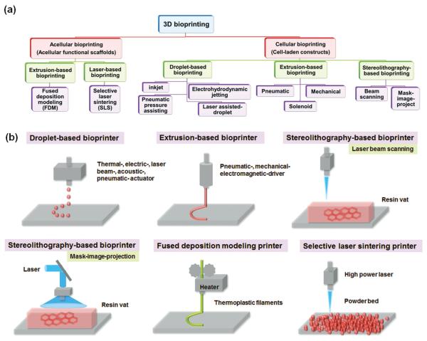
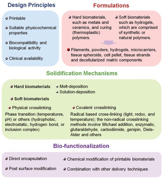
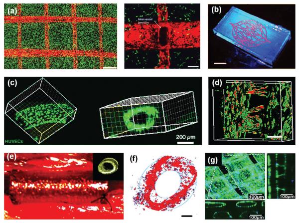
Regenerative medicine holds the promise of engineering functional tissues or organs to heal or replace abnormal and necrotic tissues/organs, offering hope for filling the gap between organ shortage and transplantation needs. Three-dimensional (3D) bioprinting is evolving into an unparalleled biomanufacturing technology due to its high-integration potential for patient-specific designs, precise and rapid manufacturing capabilities with high resolution, and unprecedented versatility. It enables precise control over multiple compositions, spatial distributions, and architectural accuracy/complexity, therefore achieving effective recapitulation of microstructure, architecture, mechanical properties, and biological functions of target tissues and organs. Here we provide an overview of recent advances in 3D bioprinting technology, as well as design concepts of bioinks suitable for the bioprinting process. We focus on the applications of this technology for engineering living organs, focusing more specifically on vasculature, neural networks, the heart and liver. We conclude with current challenges and the technical perspective for further development of 3D organ bioprinting.

Keywords: 3D bioprinting; biomaterials; neural regeneration; organ regeneration; regenerative medicine; vascularization.


Figures

Figure 1
Figure 1
Schematic diagram outlining information covered in this review. Reproduced with permission.[139] Copyright 2015, the American Association for the Advancement of Science.
Figure 2
Figure 2
(a) A tree-diagram of the various 3D bioprinting techniques and (b) Simplified illustrations of typical 3D bioprinting techniques for tissue/organ regeneration.
Figure 3
Figure 3
Design of bioinks for 3D bioprinting, including design principles, formulations, solidification mechanisms and bio-functionalization.
Figure 4
Figure 4
(a) 3D printed perfusable vascularized tissue constructs. A confocal z-stack montage demonstrating HUVECs (expressing mCherry, red) were residing in the vascular space with 10T1/2 cells (expressing EGFP, green) uniformly distributed throughout a bulk fibrin gel, after one day in culture. Scale bar, 1 mm. A partial z-stack of two intersecting channels demonstrated endothelialization of channel walls and across the intervessel junction, while in the surrounding bulk gel 10T1/2 cells are seen beginning to spread out in three dimensions. Reproduced with permission.[125] Copyright 2012, Nature Publishing Group. (b) Fluorescent image of a 3D microvascular network fabricated via omnidirectional printing of a fugitive ink (dyed red) within a photopolymerized Pluronic F127-diacrylate matrix. (Scale bar = 10 mm) Reproduced with permission.[95] Copyright 2011, Wiley-VCH. (c) Confocal image of live HUVEC cells lining the microchannel walls using the same fugitive ink method. Reproduced with permission.[124] Copyright 2014, Wiley-VCH. (d) Confocal fluorescence images of hMSCs and HUVECs co-cultured on various scaffolds in a static culture condition for 5 days. hMSCs were labeled with cell tracker green, and HUVECs were stained with cell tracker red. The scale bars indicate 200 μm. Reproduced with permission.[85] Copyright 2016, Wiley-VCH. (e) 3D-printed PPF scaffolds as venous interposition grafts at the time of in vivo implantation. Reproduced with permission.[130] Copyright 2016, Wiley-VCH. (f) Confocal fluorescence images of hMSCs and HUVECs co-cultured in designed vascular channel regions for 1 week. HUVECs encapsulated in the hydrogel were inclined to aggregate and migrate to form annular ring patterns along the channel. The scale bars indicate 200 μm. Reproduced with permission.[87] Copyright 2016, Wiley-VCH. (g) Confocal microscopy images show interconnected structures of the encapsulated HUVECs after migrating to outer regions of the bioprinted fibers at day10. Reproduced with permission.[136] Copyright 2015, Wiley-VCH.
Figure 5
Figure 5
(a) A PEG nerve guide made with a wall thickness of 50 mm by μSLA. The PEG nerve guide was implanted in to a Thy-1-YFP-H common fibular mouse, small gap, 3 mm injury model. The nerve graft repair image illustrated intervals marked with sample axon tracing from 4.0 mm interval position back to 0.0 mm (start) interval. The number of axons at each interval was counted to obtain a sprouting index value; axons were traced from distal intervals back to 0.0 mm, or a branch point with a previously traced axon (as highlighted in expanded sections with green circles), to calculate percentage of unique start axons represented at each interval. Reproduced with permission.[162] Copyright 2015, Elsevier. (b) A patient’s sciatic nerve was reconstructed based on MR neurography, and then a personalized nerve guidance conduit (NGC) was fabricated. The images show an intraoperative photograph of the NGCs for nerve regeneration in a rat sciatic nerve transection model with 10 mm gap, and the general observations of the regenerated sciatic nerve at 16 weeks post-surgery. Reproduced with permission.[166] Copyright 2016, Nature Publishing Group. (c) 3D printed graphene nerve graft conduit at various sizes. Photograph of tubular nerve conduit that was implanted into a human cadaver via longitudinal transection and wrapped around the ulnar nerve (white arrows). The nerve conduit was then sutured closed along the previously described longitudinal transection (white dotted line) as well as to the surrounding epinerium and nerve tissue (inset, yellow circle). Excess 3DG nerve conduit length was then cut with surgical shears to expose additional nerve tissue. Reproduced with permission.[167] Copyright 2015, American Chemical Society. (d) SEM image of a 3D printed hollow nerve pathway displaying an axially oriented physical cue on the luminal surface. Photograph of an implanted 3D printed nerve guide prior to suturing. Cultured primary embryonic neurons on the 3D printed, horizontally oriented physical cue (90° reference angle) stained for tau (green), while cultured Schwann cells on the horizontally oriented physical cue (90° reference angle) stained for GFAP (green) and laminin (red). Reproduced with permission.[169] Copyright 2015, Wiley-VCH. (e) Printed gel scaffold comprising optimal 5% w/v alginate, 5% w/v carboxymethyl chitosan, and 1.5% w/v agarose. NSCs (31 d post-printing, including 21 d differentiation) stained with DAPI (blue) and expressed TUJ1 (red), with cell clusters interconnected by neurites. The lower right panel shows depth coding of cells along the Z-axis (0–59 μm). Reproduced with permission.[174] Copyright 2016, Wiley-VCH.
Figure 6
Figure 6
(a) 3D printed aortic valve conduit. Fluorescent image of first two layers of a printed aortic valve conduit; SMC for valve root were labeled by cell tracker green and VIC for valve leaflet were labeled by cell tracker red. Live/dead assay for encapsulated VIC (i) in the leaflet and SMC (iii) in valve root after 7 day culture. Representative image of immunohistochemical staining for aSMA (green) and vimentin (red), and Draq 5 counterstaining for cell nuclei (blue); Staining for VIC (ii) in the leaflet, and staining for SMC (iv) in the root. Reproduced with permission.[182] Copyright 2012, Wiley-VCH. (b) A dark field image of an explanted embryonic chick heart. A 3D image of the 5-day-old embryonic chick heart stained for fibronectin (green), nuclei (blue), and F-actin (red) and imaged with a confocal microscope. A cross section of the 3D CAD model of the embryonic heart with complex internal trabeculation based on the confocal imaging data. A cross section of the 3D printed heart in fluorescent alginate (green) showing recreation of the internal trabecular structure from the CAD model. A dark field image of the 3D printed heart with internal structure visible through the translucent heart wall via FRESH technique. Reproduced with permission.[139] Copyright 2015, the American Association for the Advancement of Science. (c) Images (5×) taken under fluorescent and bright field channels showing patterns of fluorescently labeled hiPSC-HPCs (green) in 5% GelMA and supporting cells (red) in 2.5% GelMA with 1% GMHA on day 0. Scale bars, 500 μm. Grayscale images (5×) and confocal immunofluorescence images (40×) showing albumin (Alb), E-cadherin (E-Cad), and nucleus (Dapi) staining of hiPSC-HPCs in 3D triculture constructs. Scale bars, 500 μm in bright field and 100 μm in fluorescent images. Reproduced with permission.[190] Copyright 2016, National Academy of Sciences.

References

    1. Widmaier EP, Raff H, Strang KT. Vander’s Human Physiology. McGraw-Hill Education; Boston, NY, USA: 2010.
    1. Badylak SF, Weiss DJ, Caplan A, Macchiarini P. Lancet. 2012;379:943. - PubMed
    1. Rustad KC, Sorkin M, Levi B, Longaker MT, Gurtner GC. Organogenesis. 2010;6:151. - PMC - PubMed
    1. Zhang LG, Khademhosseini A, Webster TJ. Tissue and Organ Regeneration: Advances in Micro and Nanotechnology. Pan Stanford Publishing; Stanford: 2014.
    1. Castro NJ, O’Brien CM, Zhang LG. AIChE J. 2014;60:432.
    2. Zhu W, Masood F, O’Brien J, Zhang LG. Nanomedicine. 2015;11:693. - PubMed
    3. Cui H, Zhuang X, He C, Wei Y, Chen X. Acta Biomater. 2015;11:183. - PubMed
    4. Cui HT, Liu YD, Cheng YL, Zhang Z, Zhang PB, Chen XS, Wei Y. Biomacromolecules. 2014;15:1115. - PubMed
    5. Cui HT, Shao J, Wang Y, Zhang PB, Chen XS, Wei Y. Biomacromolecules. 2013;14:1904. - PubMed
    6. Cui H, Cui L, Zhang P, Huang Y, Wei Y, Chen X. Macromol. Biosci. 2014;14:440. - PubMed