. 2017 Jan 10;114(2):328-333.
doi: 10.1073/pnas.1609142114. Epub 2016 Dec 21.

Whole-GUV patch-clamping

Affiliations

Whole-GUV patch-clamping

Matthias Garten et al. Proc Natl Acad Sci U S A. .

Abstract

Studying how the membrane modulates ion channel and transporter activity is challenging because cells actively regulate membrane properties, whereas existing in vitro systems have limitations, such as residual solvent and unphysiologically high membrane tension. Cell-sized giant unilamellar vesicles (GUVs) would be ideal for in vitro electrophysiology, but efforts to measure the membrane current of intact GUVs have been unsuccessful. In this work, two challenges for obtaining the "whole-GUV" patch-clamp configuration were identified and resolved. First, unless the patch pipette and GUV pressures are precisely matched in the GUV-attached configuration, breaking the patch membrane also ruptures the GUV. Second, GUVs shrink irreversibly because the membrane/glass adhesion creating the high-resistance seal (>1 GΩ) continuously pulls membrane into the pipette. In contrast, for cell-derived giant plasma membrane vesicles (GPMVs), breaking the patch membrane allows the GPMV contents to passivate the pipette surface, thereby dynamically blocking membrane spreading in the whole-GMPV mode. To mimic this dynamic passivation mechanism, beta-casein was encapsulated into GUVs, yielding a stable, high-resistance, whole-GUV configuration for a range of membrane compositions. Specific membrane capacitance measurements confirmed that the membranes were truly solvent-free and that membrane tension could be controlled over a physiological range. Finally, the potential for ion transport studies was tested using the model ion channel, gramicidin, and voltage-clamp fluorometry measurements were performed with a voltage-dependent fluorophore/quencher pair. Whole-GUV patch-clamping allows ion transport and other voltage-dependent processes to be studied while controlling membrane composition, tension, and shape.

Keywords: biomimetic system; electrophysiology; giant unilamellar vesicle; lipid–glass interaction; patch clamp.


Conflict of interest statement

The authors declare no conflict of interest.

Figures

Fig. 1.
Fig. 1.
Whole-GUV configuration. (A) GUV-attached mode: Adhesion between the GUV membrane (magenta) and pipette inner surface creates a high-resistance electrical seal (R > 1 GΩ). (B) Whole-GUV mode: To access the GUV interior while retaining a high seal resistance, the pipette pressure is carefully adjusted (0 < Δp = ppippbath < 50 Pa) before breaking the membrane patch with a voltage pulse at t = 0. Fluorescein (green) can then flow from the pipette into the GUV while the capacitance (C) increases because the pipette now controls the transmembrane voltage, current, and tension of the entire GUV membrane. Lipids: DPhPC + 0.1% BODIPY TR ceramide. (Scale bar: 5 μm.)
Fig. S1.
Fig. S1.
Role of pressure when breaking the membrane patch. (A) Low-pressure (Δp = ppippbath < 0): After the patch is broken (+1 s), the GUV membrane is aspirated into the pipette. (B) High-pressure (Δp > 50 Pa): The resistance drops irreversibly and a hole forms (red arrow, +1 s). All times are relative to the voltage pulse used to disrupt the patch membrane. Lipids: DPhPC supplemented with 0.1% BODIPY TR ceramide (fluorescent lipid, white/magenta). (Scale bar: 5 μm.)
Fig. 2.
Fig. 2.
Membrane spreading. (A) Conventional GUV: The membrane edge (red arrow) moves up the pipette (dashed) in the GUV-attached (t < 0 s) and whole-GUV (t > 0 s) configurations. (B) GPMV: The membrane edge (red arrow; FM4-64 fluorescence) moves in the GPMV-attached configuration (t < 0 s), but stops after the patch is broken (t > 0 s). (C) Dynamic passivation: Breaking the membrane patch allows macromolecules inside the GPMV (Top) to diffuse into the pipette (Middle), where they can adhere and block membrane spreading (Bottom). (D) GPMV without dynamic passivation: Entering the whole-GPMV configuration with a higher pipette pressure (Δp ∼ 500 Pa) pushes the GPMV contents out through a hole in the GPMV body (orange arrow). The focus was adjusted to visualize the hole (t = 10 s) and membrane edge (red arrow) moving up the pipette. (Scale bar: 5 μm.)
Fig. 3.
Fig. 3.
Whole-GUV configuration with dynamic passivation. (A) Images of a patch-clamped GUV containing beta-casein. Lipids: DPhPC + 0.1% BODIPY TR ceramide. (Scale bar: 5 μm.) (B) Resistance and capacitance as a function of time for the GUV shown in A. (C) Rate of GUV area change for conventional (n = 4) and casein-containing (n = 10) DPhPC GUVs over the first 100 s in the whole-GUV configuration (cm = 0.88 μF/cm2). (D) Total resistance 10 s before, 10 s after, and 300 s after entering the whole-GUV configuration (n = 10). Bars in C and D indicate mean and SD.
Fig. S2.
Fig. S2.
Experiment demonstrating that encapsulated casein must enter the pipette to prevent membrane spreading in the whole-GUV configuration. (A) To begin the experiment, a casein-containing DPhPC GUV (DPhPC + 0.1% by mole fluorescent BODIPY TR ceramide) was placed in the GUV-attached configuration (t = −1 s). While in the GUV-attached configuration, the pipette pressure was increased (Δp > 50 Pa) so that a voltage pulse would not only break the membrane patch but also create a pore through which the encapsulated casein (2 mg/mL) would flow out of the GUV. (B) When the membrane patch was ruptured with a brief zap, the resistance plummeted but the pore formed in the GUV (orange arrow; t = 1 s) was out of focus. (C) A clearer image of the pore was then obtained by lowering the focus below the tip of the patch pipette (orange arrow; t = +7 s). (DF) The focus was then returned to the level of pipette tip and GUV center to monitor the GUV membrane spreading up the pipette interior (t = +50 s, +100 s, and +150 s). As the GUV shrank, a bright fluorescent spot appeared at the tip of the pipette (E, F), which may be due to lipid accumulation in this region. In all images, the inner pipette surface is marked with dotted white lines, and the position of the membrane patch/edge is indicated with a red arrow. (Scale bar: 5 μm.)
Fig. S3.
Fig. S3.
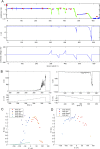
Dependence of whole-GUV resistance on holding voltage. (A) Example of whole-GUV resistance and current as holding voltage was varied in a stepwise fashion (V0 = 0 mV, ΔVi = ±10 mV, Δti = 2 s). The GUV was formed from DPhPC, and resistance was measured via an applied sinusoidal wave (blue), from a 10-mV test pulse (red), and from the current response to the voltage step (green). (B) Zoom showing the current during the first and second series of voltage steps shown in A. For each series, the current increases rapidly shortly after the voltage is stepped above a critical value. (C) Resistance vs. voltage plot for the voltage steps shown in A. (D) Resistance vs. voltage plot for a SOPC/Chol (7:3 by mole) GUV.
Fig. S4.
Fig. S4.
Pore formation under an applied voltage. (A) GUV (DPhPC + 0.1% by mole fluorescent BODIPY TR ceramide) during the application of a voltage stepping protocol (V0 = 0 mV, ΔVi = −10 mV, Δti = 2 s) at −70 mV (685 s after entering the whole-GUV configuration). After stepping to −80 mV, the current initially remained stable (B; 686 s), but shortly afterward (C; 687 s), a pore formed in the GUV causing a large negative current. (Scale bar: 5 μm.) I, current; V, voltage.
Fig. S5.
Fig. S5.
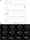
Lipid accumulation in the seal region. (A) Applied voltage, access resistance, leak resistance, and membrane capacitance as a function of time. Despite considerable lipid accumulation in the seal region and a corresponding decrease in GUV area and capacitance, the access resistance remains much smaller than the leak resistance. (B) Epifluorescence images of the GUV in A (SOPC/Chol 7:3 by mole, 0.1% BODIPY TR ceramide) held for extended intervals at −70 mV. (Scale bar: 5 μm.)
Fig. S6.
Fig. S6.
Stabilization of whole-GUV configuration by coating the patch pipette with a simple novolac resin. (A) A DPhPC GUV adhered to the pipette and formed a high-resistance seal. After the patch was ruptured (B), the membrane did not spread up the pipette interior (C). All times are relative to the voltage pulse used to disrupt the patch membrane. The fluorescence in the pipette at 531 s is due to the inclusion of 0.1% BODIPY TR ceramide into the resin. (Scale bar: 5 μm.)
Fig. 4.
Fig. 4.
GUV membrane electrical and mechanical properties. (A) Specific capacitance (Cspec; capacitance per unit area) for different conditions and membrane compositions. Colored markers correspond to individual GUVs, whereas the mean and SD (when n > 2) are plotted in black. Reported values for a hexadecane-based BLM (31), hexadecane-based DIB (32), and solvent-free planar bilayer (29) are shown for comparison. (B) Specific capacitance vs. reported membrane hydrophobic core thickness for DPhPC (33), DOPC, DOPC/Chol 8:2, SOPC, and SOPC/Chol 7:3 (34). Each marker corresponds to an individual GUV from A, whereas the solid line shows the fit to the dielectric slab model. (C) Relative capacitance change (ΔC/C) of a DPhPC GUV as membrane tension was repeatedly cycled up (orange Δ) and down (blue ∇). Lines indicate fits of Eq. 3 as the tension was increased (solid line, n = 3 ramps) and decreased (dashed line, n = 3 ramps).
Fig. 5.
Fig. 5.
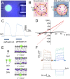
Ionic currents and voltage-clamp fluorometry. (A) GUV containing gA channels showing the perfusion (Right) and patch pipettes (Left; bright field) overlaid with fluorescence from the lipids (DPhPC + 0.1% BODIPY TR ceramide; magenta), patch pipette solution (95 mM Na+, 5 mM Chol+, 20 μM fluorescein; green), and perfusion solution (95 mM Chol+, 5 mM Na+, 40 μM cascade blue). (Scale bar: 5 μm.) (B) Schematic showing how substituting external Na+ (magenta) for impermeable Chol+ (blue) evokes an outward current through gA channels at 0 mV. (C) Perfusion of low Na+ solution (bars) evokes an outward current. (D) Current/voltage relationships from GUVs with gA (red) or without gA (black) in symmetrical solutions (dashed line) or while perfusing a low-Na+ solution (solid line). (E) Schematic of the voltage-dependent fluorophore/quencher pair, DiO and DPA. At positive/negative voltages, movement of negatively charged DPA unquenches DiO in the outer/inner leaflet. (F) Fluorescence change (ΔF/F) of a GUV containing DPA and DiO in response to voltage steps.
Fig. S7.
Fig. S7.
Photograph of the electrophysiology observation chamber. Glass coverslips form the top and bottom of the chamber, and the patch pipette enters at a shallow angle from the left.
Fig. S8.
Fig. S8.
Equivalent circuit of the whole-cell configuration. Va is the applied voltage at the pipette electrode, Cp is the pipette and head-stage capacitance, Ra is the access resistance due to the pipette, Rl is the effective resistance of seal and cell membrane, and Cm is the capacitance of the cell membrane.

Similar articles

Cited by

References

    1. Hille B. Ion Channels of Excitable Membranes. 3rd Ed Sinauer; Sunderland, MA: 2001.
    1. Hamill OP, Marty A, Neher E, Sakmann B, Sigworth FJ. Improved patch-clamp techniques for high-resolution current recording from cells and cell-free membrane patches. Pflugers Arch. 1981;391(2):85–100. - PubMed
    1. Suchyna TM, Markin VS, Sachs F. Biophysics and structure of the patch and the gigaseal. Biophys J. 2009;97(3):738–747. - PMC - PubMed
    1. Varghese A, Tenbroek EM, Coles J, Jr, Sigg DC. Endogenous channels in HEK cells and potential roles in HCN ionic current measurements. Prog Biophys Mol Biol. 2006;90(1-3):26–37. - PubMed
    1. Chandrasekhar KD, Bas T, Kobertz WR. KCNE1 subunits require co-assembly with K+ channels for efficient trafficking and cell surface expression. J Biol Chem. 2006;281(52):40015–40023. - PubMed

Publication types

LinkOut - more resources