

Development of clinical simultaneous SPECT/MRI
- PMID: 28008775
- PMCID: PMC5966197
- DOI: 10.1259/bjr.20160690
Development of clinical simultaneous SPECT/MRI
Abstract
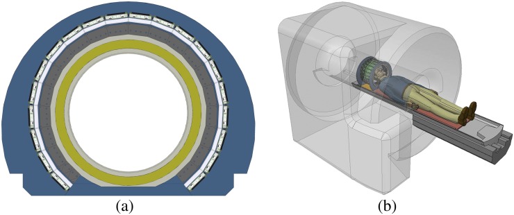
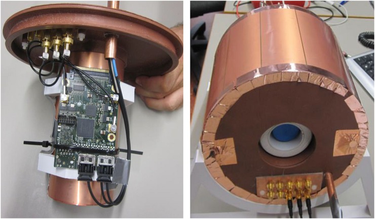
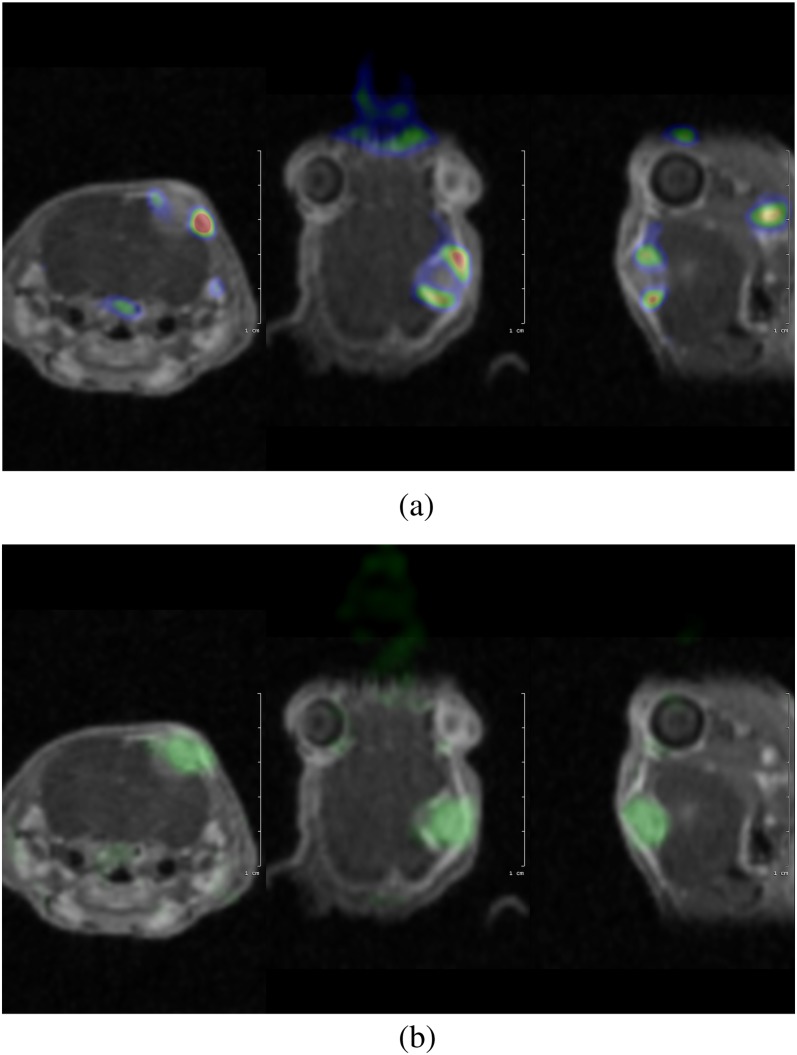
There is increasing clinical use of combined positron emission tomography and MRI, but to date there has been no clinical system developed capable of simultaneous single-photon emission computed tomography (SPECT) and MRI. There has been development of preclinical systems, but there are several challenges faced by researchers who are developing a clinical prototype including the need for the system to be compact and stationary with MRI-compatible components. The limited work in this area is described with specific reference to the Integrated SPECT/MRI for Enhanced stratification in Radio-chemo Therapy (INSERT) project, which is at an advanced stage of developing a clinical prototype. Issues of SPECT/MRI compatibility are outlined and the clinical appeal of such a system is discussed, especially in the management of brain tumour treatment.
Figures
Similar articles
-
Collimator design for a multipinhole brain SPECT insert for MRI.Med Phys. 2015 Nov;42(11):667989. doi: 10.1118/1.4934371. Med Phys. 2015. PMID: 26520758
-
The role of preclinical SPECT in oncological and neurological research in combination with either CT or MRI.Eur J Nucl Med Mol Imaging. 2014 May;41 Suppl 1(Suppl 1):S36-49. doi: 10.1007/s00259-013-2685-3. Eur J Nucl Med Mol Imaging. 2014. PMID: 24895751 Free PMC article. Review.
-
Analysis of eddy currents induced by transverse and longitudinal gradient coils in different tungsten collimators geometries for SPECT/MRI integration.Magn Reson Med. 2015 Dec;74(6):1780-9. doi: 10.1002/mrm.25534. Epub 2014 Nov 26. Magn Reson Med. 2015. PMID: 25426597
-
PET-MR and SPECT-MR multimodality probes: Development and challenges.Theranostics. 2018 Nov 29;8(22):6210-6232. doi: 10.7150/thno.26610. eCollection 2018. Theranostics. 2018. PMID: 30613293 Free PMC article. Review.
-
Instrumentation in molecular imaging.J Nucl Cardiol. 2016 Dec;23(6):1343-1347. doi: 10.1007/s12350-016-0498-z. Epub 2016 Apr 12. J Nucl Cardiol. 2016. PMID: 27072005 Review.
Cited by
-
Respiratory motion compensation in interventional liver SPECT using simultaneous fluoroscopic and nuclear imaging.Med Phys. 2019 Aug;46(8):3496-3507. doi: 10.1002/mp.13653. Epub 2019 Jun 27. Med Phys. 2019. PMID: 31183868 Free PMC article.
-
System Modeling and Evaluation of a Prototype Inverted-Compound Eye Gamma Camera for the Second Generation MR Compatible SPECT.Nucl Instrum Methods Phys Res A. 2020 Feb 21;954:162046. doi: 10.1016/j.nima.2019.04.001. Epub 2019 Apr 17. Nucl Instrum Methods Phys Res A. 2020. PMID: 32773914 Free PMC article.
-
What scans we will read: imaging instrumentation trends in clinical oncology.Cancer Imaging. 2020 Jun 9;20(1):38. doi: 10.1186/s40644-020-00312-3. Cancer Imaging. 2020. PMID: 32517801 Free PMC article. Review.
-
Neuroimaging with SPECT-MRI: a myth or reality?AIMS Neurosci. 2023 Mar 31;10(1):52-55. doi: 10.3934/Neuroscience.2023004. eCollection 2023. AIMS Neurosci. 2023. PMID: 37077955 Free PMC article. No abstract available.
-
Optimization of the Pixel Design for Large Gamma Cameras Based on Silicon Photomultipliers.Sensors (Basel). 2024 Sep 19;24(18):6052. doi: 10.3390/s24186052. Sensors (Basel). 2024. PMID: 39338796 Free PMC article.
References
-
- Cherry SR, Louie AY, Jacobs RE. The integration of positron emission tomography with magnetic resonance imaging. Proc IEEE 2008; 96: 416–38. doi: 10.1109/jproc.2007.913502 - DOI
-
- Pichler BJ, Judenhofer MS, Catana C, Walton JH, Kneilling M, Nutt RE, et al. Performance test of an LSO-APD detector in a 7-T MRI scanner for simultaneous PET/MRI. J Nucl Med 2006; 47: 639–47. - PubMed
MeSH terms
Substances
Grants and funding
LinkOut - more resources
Full Text Sources
Other Literature Sources
Medical
