. 2017 Feb 13;375(2086):20150354.
doi: 10.1098/rsta.2015.0354.

Micromechanics of sea ice frictional slip from test basin scale experiments

Affiliations

Micromechanics of sea ice frictional slip from test basin scale experiments

Peter R Sammonds et al. Philos Trans A Math Phys Eng Sci. .

Abstract

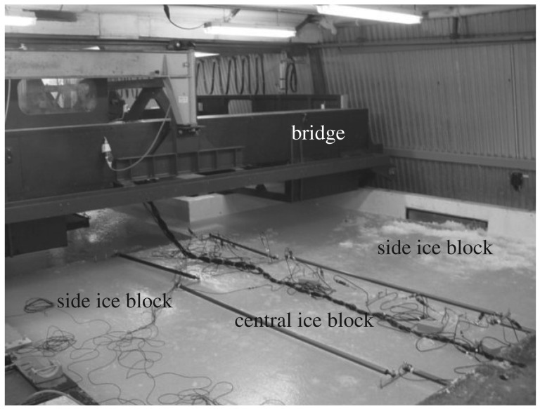
We have conducted a series of high-resolution friction experiments on large floating saline ice floes in an environmental test basin. In these experiments, a central ice floe was pushed between two other floes, sliding along two interfacial faults. The frictional motion was predominantly stick-slip. Shear stresses, normal stresses, local strains and slip displacement were measured along the sliding faults, and acoustic emissions were monitored. High-resolution measurements during a single stick-slip cycle at several positions along the fault allowed us to identify two phases of frictional slip: a nucleation phase, where a nucleation zone begins to slip before the rest of the fault, and a propagation phase when the entire fault is slipping. This is slip-weakening behaviour. We have therefore characterized what we consider to be a key deformation mechanism in Arctic Ocean dynamics. In order to understand the micromechanics of sea ice friction, we have employed a theoretical constitutive relation (i.e. an equation for shear stress in terms of temperature, normal load, acceleration, velocity and slip displacement) derived from the physics of asperity-asperity contact and sliding (Hatton et al. 2009 Phil. Mag. 89, 2771-2799 (doi:10.1080/14786430903113769)). We find that our experimental data conform reasonably with this frictional law once slip weakening is introduced. We find that the constitutive relation follows Archard's law rather than Amontons' law, with [Formula: see text] (where τ is the shear stress and σn is the normal stress) and n = 26/27, with a fractal asperity distribution, where the frictional shear stress, τ = ffractal Tmlws, where ffractal is the fractal asperity height distribution, Tml is the shear strength for frictional melting and lubrication and ws is the slip weakening. We can therefore deduce that the interfacial faults failed in shear for these experimental conditions through processes of brittle failure of asperities in shear, and, at higher velocities, through frictional heating, localized surface melting and hydrodynamic lubrication.This article is part of the themed issue 'Microdynamics of ice'.

Keywords: micromechanics; scaling; sea ice friction.


Figures

Figure 1.
Figure 1.
Photograph of the HSVA Arctic environmental test basin showing our experimental set-up for a lubricated double-direct shear test on floating saline ice floes. The bridge across the basin is used to push a central block of ice between two side blocks, which apply a normal load, provided by side pusher panels (bottom left). The basin is 30 m long × 6 m wide. This is shown schematically in figure 4.
Figure 2.
Figure 2.
Temperature profiles of the middle of the ice sheet are shown for two experiments discussed in the text done on day 1 (temp. T1) and day 2 (temp. T2) of the test programme. The nominal air temperatures were −7°C and −6°C, respectively.
Figure 3.
Figure 3.
(a) Pair of vertical thin sections taken through the thickness of the ice sheet and two horizontal thin sections taken at 15 mm depth (top) and 90 mm depth (bottom) in the plane of the ice sheet, viewed under crossed polarizing lenses. The grid size is 10 × 10 mm. (See figure 9 and electronic supplementary material B of Hatton et al. [6].) (b) Profile of a replica surface and asperity height distribution taken from the frictional sliding surface. The direction of sliding is x and z is the vertical direction in the ice sheet. The area of the surface sampled is 10 × 10 mm. (Online version in colour.)
Figure 4.
Figure 4.
Schematic diagram of the double-direct shear test in the HSVA environmental test basin. R1–R8 denote the positions of eight pairs of stress sensors mounted as two limbs of rosettes which measured local shear stresses. Six transverse displacement transducers mounted at 1 m intervals measured local normal displacement. D1–D8 denote the position of eight longitudinal displacement transducers, mounted to measure slip displacement. Eight acoustic transducers (not shown) recorded acoustic emissions. (Online version in colour.)
Figure 5.
Figure 5.
The shear stress τ4 in the central ice floe, during a single stick–slip event in experiment number 1–4, is plotted, as points, against the displacement D2; the subscripts ‘4’ and ‘2’ index the positions along the fault where the shear stress sensor and displacement were measured; these are roughly equivalent positions (figure 4). Data were collected at 5000 samples per second, and the full sampling frequency is used in this plot. D2D2(D2start0) is an arbitrary origin for displacement.
Figure 6.
Figure 6.
(a,b) The shear stress τi in the central ice floe, during a single stick–slip event in experiment number 2–8, is plotted, as points, against the position x, where the shear stress sensor was positioned and the time t; the subscript ‘i’ indexes the position x. Data were collected at 5000 samples per second, and the full sampling frequency is used in this plot. (c) Schematic map of the processes taking place on the fault, as a function of position and time.
Figure 7.
Figure 7.
Five pairs of variables, from among the shear stress τ4 in the central ice sheet, the displacement D2 of the central ice sheet, the velocity formula image of the central ice sheet, and the acceleration formula image 
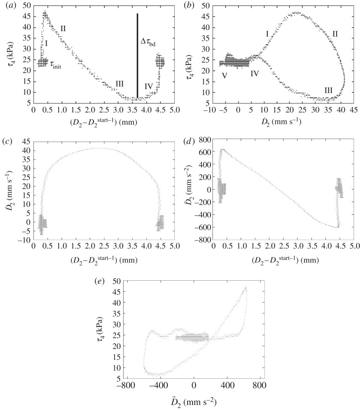
of the central ice sheet, during a single stick–slip event in experiment 1–4, are plotted, as points; the subscripts ‘4’ and ‘2’ index the positions along the fault where the shear stress sensor and displacement were measured; these are roughly equivalent positions (figure 4). D2start-1 is an arbitrary origin for displacement. (a) Shear stress is plotted against displacement. (b) Shear stress is plotted against velocity. (c) Velocity is plotted against displacement. (d) Acceleration is plotted against displacement. (e) Shear stress is plotted against acceleration.
Figure 8.
Figure 8.
Schematic diagram (from figure 7). The behaviour shows an initial phase I where peak shear stress is attained, an accelerating phase II, a decelerating phase III, a re-strengthening phase IV, and in phase V a time-dependent strengthening.
Figure 9.
Figure 9.
Lubricated sliding asperity contact model. Two levels of asperities are shown (medium and smaller size, with radii of curvature, RB and RC, respectively). Melt is generated at the contact and expelled. X is the distance the ice floe has to slide between a fluid element being generated by melting at the leading edge of an individual asperity contact and being expelled at the trailing edge. D0 is a characteristic displacement representing the slip required for complete replacement of the real asperity contact area. Y is the contact destruction length representing the typical individual asperity contact during sliding.
Figure 10.
Figure 10.
The dependent variable, shear stress τi, in the central ice, during all the HSVA Hamburg experiments, is plotted. (a) Shear stress is plotted against displacement. (b) Shear stress is plotted against velocity. (c) Coefficient of friction is plotted against normal load. (d) Shear stress is plotted against normal load.
Figure 11.
Figure 11.
Comparison of the experimental data of Schulson & Fortt [23] (shown as points with error bars) with predictions from the theoretical model [6] (line). The coefficient of kinetic friction is plotted as a function of sliding velocity.

References

    1. Seymour-Pierce A, Lishman B, Sammonds P. 2017. Recrystallization and damage of ice in winter sports. Phil. Trans. R. Soc. A 375, 20150353 (10.1098/rsta.2015.0353) - DOI - PubMed
    1. Scourfield S, Sammonds P, Lishman L, Marchenko M. 2015. The effect of ice rubble on ice–ice sliding. In Proc 23rd Int. Conf. Port and Ocean Engineering Under Arctic Conditions, Trondheim, Norway, 14–18 June 2015.
    1. McCarthy C, Savage H, Nettles M. 2017. Temperature dependence of ice-on-rock friction at realistic glacier conditions. Phil. Trans. R. Soc. A 375, 20150348 (10.1098/rsta.2015.0348) - DOI - PMC - PubMed
    1. Weiss J, Dansereau V. 2017. Linking scales in sea ice mechanics. Phil. Trans. R. Soc. A 375, 20150352 (10.1098/rsta.2015.0352) - DOI - PMC - PubMed
    1. Middleton CA, Grindrod PM, Sammonds PR. 2017. The effect of rock particles and D2O replacement on the flow behaviour of ice. Phil. Trans. R. Soc. A 375, 20150349 (10.1098/rsta.2015.0349) - DOI - PMC - PubMed

LinkOut - more resources