. 2017 Jan 1;22(1):16003.
doi: 10.1117/1.JBO.22.1.016003.

Fluorescence laminar optical tomography for brain imaging: system implementation and performance evaluation

Affiliations

Fluorescence laminar optical tomography for brain imaging: system implementation and performance evaluation

Mehdi Azimipour et al. J Biomed Opt. .

Abstract

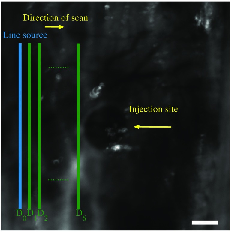
We present our effort in implementing a fluorescence laminar optical tomography scanner which is specifically designed for noninvasive three-dimensional imaging of fluorescence proteins in the brains of small rodents. A laser beam, after passing through a cylindrical lens, scans the brain tissue from the surface while the emission signal is captured by the epi-fluorescence optics and is recorded using an electron multiplication CCD sensor. Image reconstruction algorithms are developed based on Monte Carlo simulation to model light–tissue interaction and generate the sensitivity matrices. To solve the inverse problem, we used the iterative simultaneous algebraic reconstruction technique. The performance of the developed system was evaluated by imaging microfabricated silicon microchannels embedded inside a substrate with optical properties close to the brain as a tissue phantom and ultimately by scanning brain tissue in vivo. Details of the hardware design and reconstruction algorithms are discussed and several experimental results are presented. The developed system can specifically facilitate neuroscience experiments where fluorescence imaging and molecular genetic methods are used to study the dynamics of the brain circuitries.


Figures

Fig. 1
Fig. 1
FLOT measurement geometry and source–detector configuration in a line pattern illumination. The emitted fluorescent signal is collected from up to nine detector arrays parallel to the line illumination with separations of 0.0 to 1.6 mm. Seven source–detector pairs with the separation between 0.0 to 1.2 mm are shown.
Fig. 2
Fig. 2
(a) Block diagram of the FLOT system. Collimated laser light passes through a cylindrical lens for line illumination. A dichroic mirror separates the illumination from the imaging path. Excitation light is focused on the sample by a scan-lens. A pair of galvanometers is used to scan and descan the tissue. The emitted light is reflected by the dichroic beam splitter and passes through a narrow-band emission optical filter and then imaged on the EMCCD sensor. (b) Snapshots of the developed FLOT system.
Fig. 3
Fig. 3
Simulated sensitivity matrix using MC light propagation model for six different source–detector separations in a scattering medium with the optical properties: μa=1  mm1, μs=9  mm1, and g=0.9.
Fig. 4
Fig. 4
(a) Cross section of the microfluidic phantom, a channel with the size of (200  μm×150  μm) is embedded at the depth of 1 mm, (b) and (c) final phantom and its image under the microscope. The channel was filled with FAD solution as fluorescent liquid using a syringe pump.
Fig. 5
Fig. 5
(a) Schematic of the double-integrating sphere setup used to measure the optical properties of the microfabricated tissue phantoms. (b) A snapshot from the double-integrating sphere optical setup.
Fig. 6
Fig. 6
Experimental raw data obtained by the detectors number 1 to 6 for a microchannel phantom with a rectangular cross section (200  μm×25  μm) embedded at the depth of 800  μm.
Fig. 7
Fig. 7
The reconstruction results of two phantoms, one with the channel size of (200  μm×25  μm) at the depth of 800  μm, and one with the channel size of (150  μm×25  μm) at the depth of 1.2 mm. The exact depth of the microchannel was measured by the OCT system and is shown on the left panel for comparison. A 2-D ZX cross section of the reconstructed channel by SART algorithm is shown on the right panel.
Fig. 8
Fig. 8
The 3-D reconstructed image of a microchannel at the depth of 1200  μm filled with FAD solution.
Fig. 9
Fig. 9
In vivo experiments were conducted through a thinned-skull rat brain transfected with GFP. The returning fluorescent light was captured by the successively defined detectors (D0 to D6) while the laser beam scans the tissue (scale bar is 500  μm).
Fig. 10
Fig. 10
Experimental raw data of an in vivo scan of a rat cortex through thinned skull, obtained by detectors number 1 to 9. The injection was performed in the right hemisphere, at the depth of 800  μm, with GFP.
Fig. 11
Fig. 11
Experimental results of in vivo scans of rat brains with the injection depth of (A) 800  μm in the right hemisphere, (B) 800  μm in the left hemisphere, and (C) 800  μm in the left hemisphere. In (A) and (B), the gene expression was successful: (a) a confocal microscopy image of a rat brain’s slice close to the site of injection, (b) FLOT reconstruction result, (c) curve displays fluorescence signal as a function of depth detected by the single optical fiber probe system, (d) superimposed image of the reconstruction result and the confocal microscopy image. In (C), the gene expression was not successful: (a) curve displays fluorescence signal as a function of depth detected by the single optical fiber probe system, (b) a confocal microscopy image of a rat brain slice close to the site of injection.
Fig. 12
Fig. 12
Spatial and temporal distribution of fluorescent signal due to injection of 100  μA electrical stimulation through a graphene array with 150  μm site diameter in a transgenic GCaMP6f mouse brain.

References

    1. Hillman E. M. C., “Optical brain imaging in vivo: techniques and applications from animal to man,” J. Biomed. Opt. 12(5), 051402 (2007).JBOPFO10.1117/1.2789693 - DOI - PMC - PubMed
    1. Choi Y., et al. , “Optical imaging with the use of a scattering lens,” IEEE J. Sel. Top. Quantum Electron. 20(2), 61–73 (2014).IJSQEN10.1109/JSTQE.2013.2275942 - DOI
    1. Rajadhyaksha M., Anderson R. R., Webb R. H., “Video-rate confocal scanning laser microscope for imaging human tissues in vivo,” Appl. Opt. 38(10), 2105–2115 (1999).APOPAI10.1364/AO.38.002105 - DOI - PubMed
    1. Denk W., Strickler J. H., Webb W. W., “Two-photon laser scanning fluorescence microscopy,” Science 248(4951), 73–76 (1990).SCIEAS10.1126/science.2321027 - DOI - PubMed
    1. Hillman E. M. C., et al. , “Laminar optical tomography: demonstration of millimeter-scale depth-resolved imaging in turbid media,” Opt. Lett. 29(14), 1650–1652 (2004).OPLEDP10.1364/OL.29.001650 - DOI - PubMed