. 2017 Jan 10;83(1):3-27.
doi: 10.1002/fld.4248. Epub 2016 May 25.

SPH modelling of depth-limited turbulent open channel flows over rough boundaries

Affiliations

SPH modelling of depth-limited turbulent open channel flows over rough boundaries

Ehsan Kazemi et al. Int J Numer Methods Fluids. .

Abstract

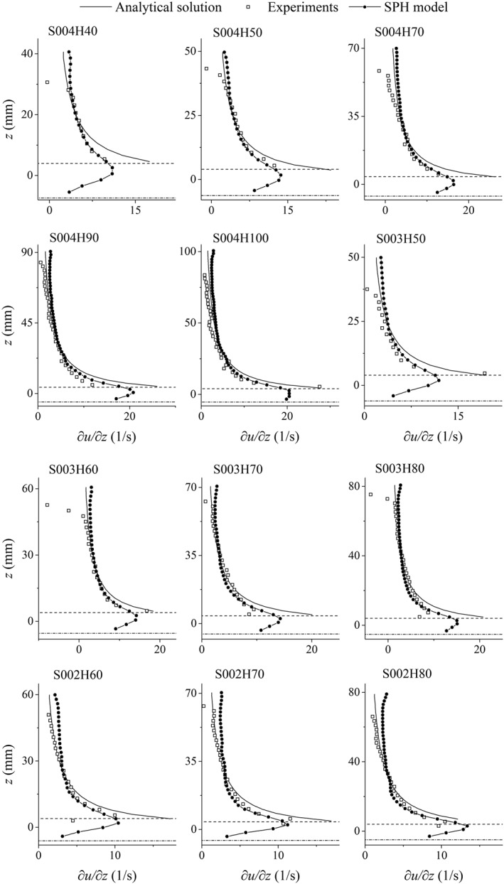
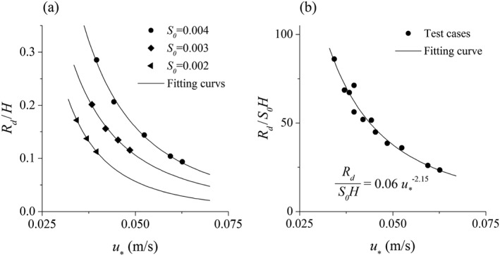
A numerical model based on the smoothed particle hydrodynamics method is developed to simulate depth-limited turbulent open channel flows over hydraulically rough beds. The 2D Lagrangian form of the Navier-Stokes equations is solved, in which a drag-based formulation is used based on an effective roughness zone near the bed to account for the roughness effect of bed spheres and an improved sub-particle-scale model is applied to account for the effect of turbulence. The sub-particle-scale model is constructed based on the mixing-length assumption rather than the standard Smagorinsky approach to compute the eddy-viscosity. A robust in/out-flow boundary technique is also proposed to achieve stable uniform flow conditions at the inlet and outlet boundaries where the flow characteristics are unknown. The model is applied to simulate uniform open channel flows over a rough bed composed of regular spheres and validated by experimental velocity data. To investigate the influence of the bed roughness on different flow conditions, data from 12 experimental tests with different bed slopes and uniform water depths are simulated, and a good agreement has been observed between the model and experimental results of the streamwise velocity and turbulent shear stress. This shows that both the roughness effect and flow turbulence should be addressed in order to simulate the correct mechanisms of turbulent flow over a rough bed boundary and that the presented smoothed particle hydrodynamics model accomplishes this successfully.

Keywords: SPH; drag force; inflow/outflow boundaries; open channel flow; rough bed; turbulence.


Figures

Figure 1
Figure 1
A schematic view of the computational domain and boundary conditions.
Figure 2
Figure 2
(a, b) Inflow boundary treatment.
Figure 3
Figure 3
A schematic view of the bed drag force model.
Figure 4
Figure 4
Calibration and validation of the model in terms of the effective roughness height versus the water depth.
Figure 5
Figure 5
Uniform flow condition (test case S004H50): (a) instantaneous streamwise velocity; (b) instantaneous pressure; (c) time‐averaged streamwise velocity; and (d) time‐averaged pressure.
Figure 6
Figure 6
Uniformity and steadiness of the flow (test case S004H50): (a) time‐averaged velocity in three sections through the channel and (b) space‐averaged velocity in three times with 15‐s intervals.
Figure 7
Figure 7
Distribution of the time‐averaged streamwise velocity over depth. Dash‐dotted and dashed lines show the level of the numerical bed (zero‐velocity plane) and the crest of the roughness zone, respectively.
Figure 8
Figure 8
Mean absolute error (MAE) of the streamwise velocity in the lower 20%, middle 60% and upper 20% of the depth.
Figure 9
Figure 9
Distribution of the gradient of the time‐averaged streamwise velocity over depth. Dash‐dotted and dashed lines show the level of the numerical bed (zero‐velocity plane) and the crest of the roughness zone, respectively.
Figure 10
Figure 10
Mean absolute error (MAE) of the streamwise velocity gradient in the lower 20%, middle 60% and upper 20% of the depth.
Figure 11
Figure 11
Relative roughness height against shear velocity: (a) relationship between Rd/H and u * for different bed slopes and (b) relationship between Rd/S 0 H and u * for all tests.
Figure 12
Figure 12
Distribution of the drag‐induced shear term in the effective roughness zone (solid line). Dash‐dotted and dotted lines show the level of the numerical bed (zero‐velocity plane) and the crest of the roughness zone, respectively.
Figure 13
Figure 13
Velocity profiles of tests with bed slopes (a) 0.004, (b) 0.003 and (c) 0.002. The dashed lines show the level of the roughness crest, and the solid half circles schematically depict the roughness element.
Figure 14
Figure 14
Distribution of the mixing length in two cases with the same depth (H = 50 mm) and different effective roughness heights (R d,2 > R d,1). The zero reference of the mixing length is on the numerical bed level (zero‐velocity plane), and the dotted line shows the crest of the roughness zone.
Figure 15
Figure 15
Distributions of the normalized turbulent shear stress with depth.
Figure 16
Figure 16
Time‐averaged streamwise velocity obtained from the present mixing‐length model compared with the one obtained from the Smagorinsky model with Cs = 0.15 and the experimental data for test cases S004H50, S003H70 and S002H60 (vertical axis z is in logarithmic scale).
Figure 17
Figure 17
The x‐z component of the turbulent shear stress obtained from the present mixing‐length model compared with the one obtained from the Smagorinsky model with Cs = 0.15 and the analytical profiles for test cases S004H50, S003H70 and S002H60.

References

    1. Nikora V, Koll K, McEwan I, McLean S, Dittrich A. Velocity distribution in the roughness layer of rough‐bed flows. Journal of Hydraulic Engineering 2004; 130:1036–1042.
    1. Nicholas AP. Computational fluid dynamics modelling of boundary roughness in gravel‐bed rivers: an investigation of the effects of random variability in bed elevation. Earth Surface Processes and Landforms 2001; 26:345–362.
    1. Smagorinsky J. General circulation experiments with the primitive equations. I. The basic experiment. Monthly Weather Review 1963; 91:99–164.
    1. Van Driest ER. On turbulent flow near a wall. Journal of the. Atmospheric Sciences 1956; 23:1007–1011.
    1. Rotta J. Turbulent boundary layers in incompressible flow. Progress in Aerospace Sciences 1962; 2:73–82.

LinkOut - more resources