Review
. 2016 Oct;8(Suppl 9):S716-S730.
doi: 10.21037/jtd.2016.09.56.

Techniques of stapler-based navigational thoracoscopic segmentectomy using virtual assisted lung mapping (VAL-MAP)

Affiliations
Review

Techniques of stapler-based navigational thoracoscopic segmentectomy using virtual assisted lung mapping (VAL-MAP)

Masaaki Sato et al. J Thorac Dis. 2016 Oct.

Abstract

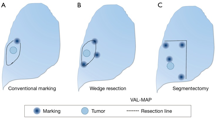
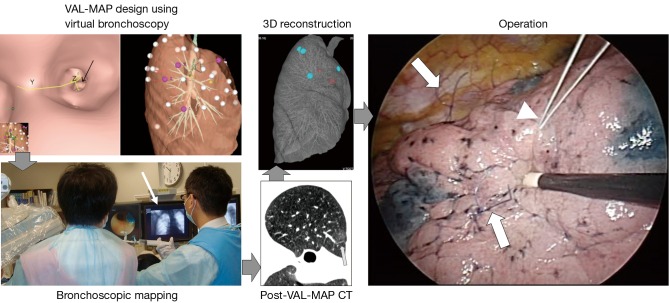
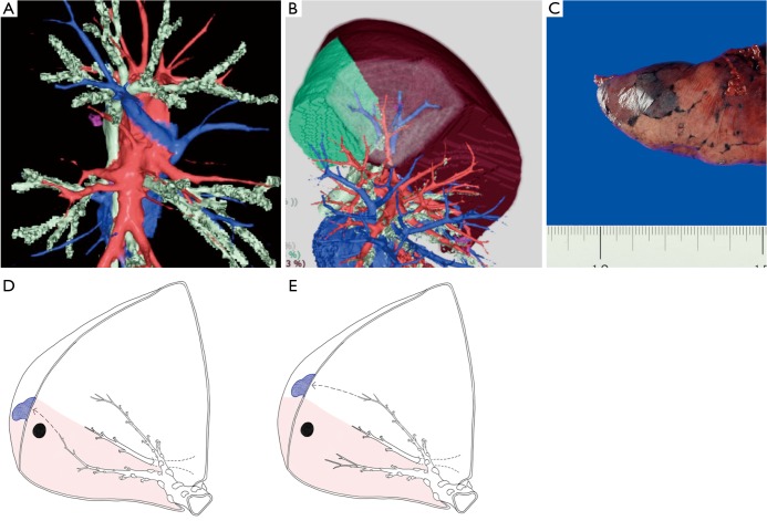
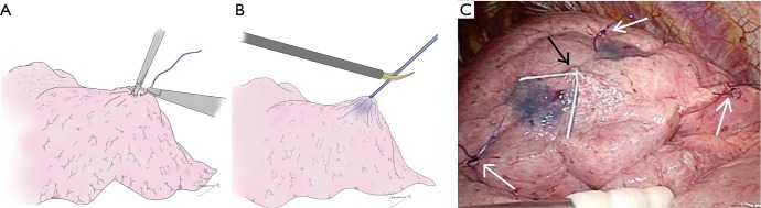
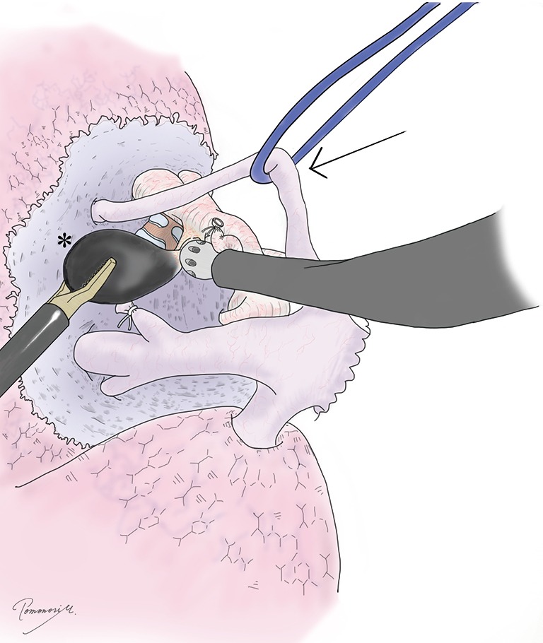
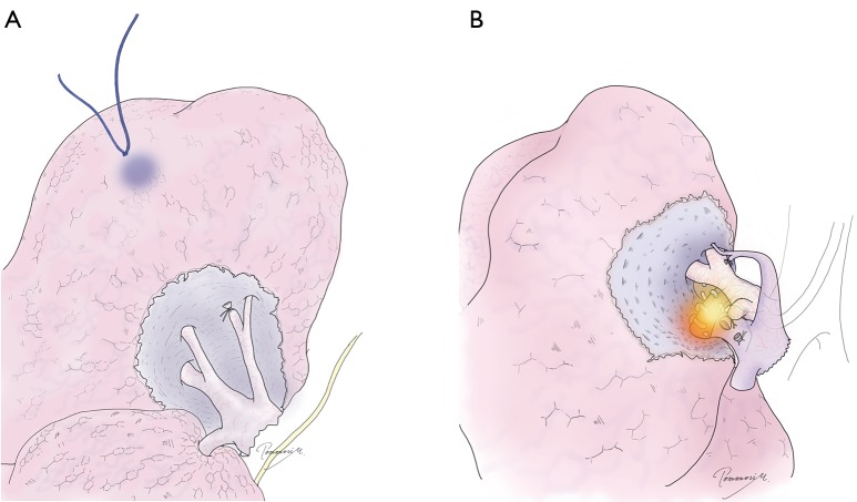
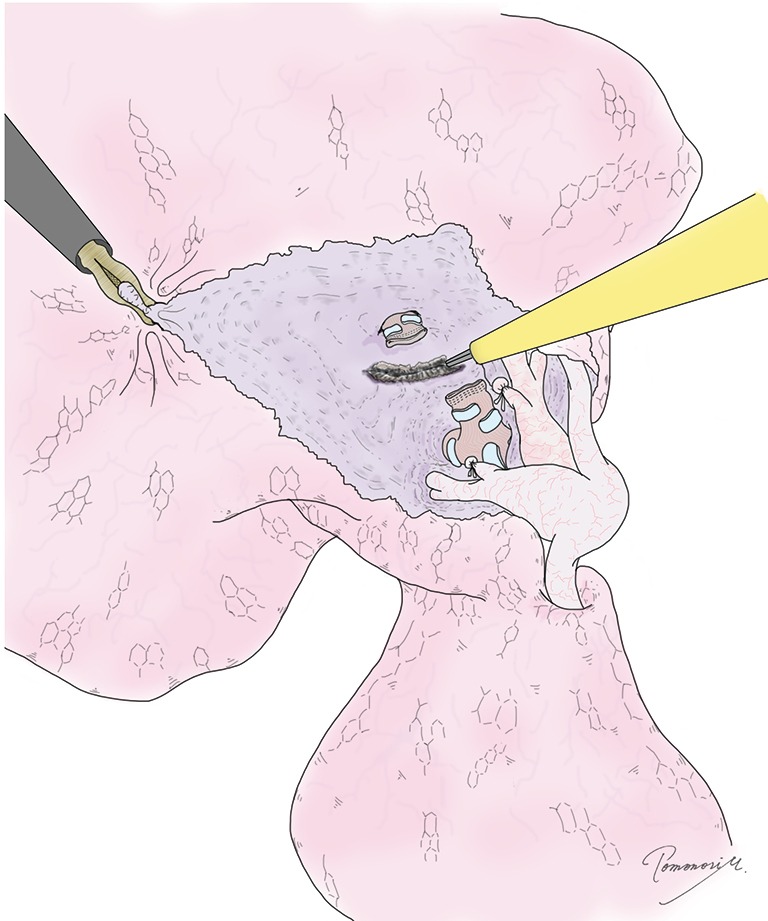
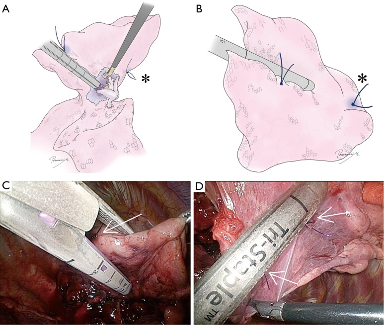
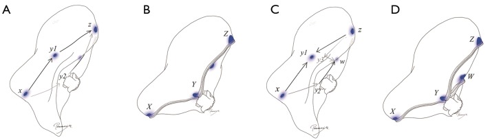
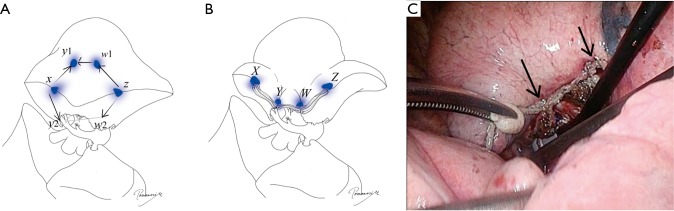
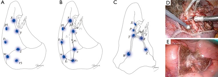
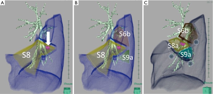
Anatomical segmentectomies play an important role in oncological lung resection, particularly for ground-glass types of primary lung cancers. This operation can also be applied to metastatic lung tumors deep in the lung. Virtual assisted lung mapping (VAL-MAP) is a novel technique that allows for bronchoscopic multi-spot dye markings to provide "geometric information" to the lung surface, using three-dimensional virtual images. In addition to wedge resections, VAL-MAP has been found to be useful in thoracoscopic segmentectomies, particularly complex segmentectomies, such as combined subsegmentectomies or extended segmentectomies. There are five steps in VAL-MAP-assisted segmentectomies: (I) "standing" stitches along the resection lines; (II) cleaning hilar anatomy; (III) confirming hilar anatomy; (IV) going 1 cm deeper; (V) step-by-step stapling technique. Depending on the anatomy, segmentectomies can be classified into linear (lingular, S6, S2), V- or U-shaped (right S1, left S3, S2b + S3a), and three dimensional (S7, S8, S9, S10) segmentectomies. Particularly three dimensional segmentectomies are challenging in the complexity of stapling techniques. This review focuses on how VAL-MAP can be utilized in segmentectomy, and how this technique can assist the stapling process in even the most challenging ones.

Keywords: Lung cancer; bronchoscopy; marking; segmentectomy; video-assisted thoracoscopic surgery (VATS).


Conflict of interest statement

The authors have no conflicts of interest to declare.

Figures

Figure 1
Figure 1
From marking to mapping using VAL-MAP. (A) A conventional marking. The location of a barely identifiable tumor is estimated based only on a single marking, and then the resection line is determined; (B) VAL-MAP-assisted wedge resection. Multiple markings of VAL-MAP provide geometric information on the lung, indicating the location of the tumor and oncologically ideal resection lines; (C) VAL-MAP-assisted segmentectomy. Multiple markings of VAL-MAP can also indicate resection lines for segmentectomy. The figures are reproduced with permission from Cancer Res Front 2016;2:85-104. VAL-MAP, virtual assisted lung mapping.
Figure 2
Figure 2
Steps in VAL-MAP. In general, VAL-MAP and the following surgery are conducted in five steps. Following design of the lung “map” using virtual bronchoscopy, VAL-MAP is usually conducted on the same day or a day before surgery. CT scan after VAL-MAP is taken within 2–3 hours after VAL-MAP, showing actual locations of markings (arrow). Using a radiology workstation, 3D images are reconstructed based on post-VAL-MAP CT scan, reflecting actual locations of markings. The operation field should look the same as that of 3D images. In segmentectomy, the “standing” stiches (arrows) are placed along resection lines, referring to the lung “map” made by VAL-MAP. Another stich indicating the location of the tumor may also be placed using a stich with different color (arrow head). Note that the “standing” stiches are not necessarily placed at the dye markings made by VAL-MAP; dye markings provide geometric information, based on which ideal resection lines are determined and then the resection lines are indicated by the “standing” stiches. VAL-MAP, virtual assisted lung mapping.
Figure 3
Figure 3
The principle of VAL-MAP-assisted segmentectomy. (A) A three-dimensional image made by a radiology workstation (Synapse Vincent®) showing hilar vascular structures; (B) a lung resection analysis of Synapse Vincent showing the area of subsegments and VAL-MAP markings in combination with hilar structures; (C) a good marking should not disseminate across the intersegmental plane, staining only a single lobule; (D) a marking is placed close to the intersegmental line from a bronchus inside the target segment (shadowed area); (E) a marking is placed close to the intersegmental line from a bronchus outside the target segment (shadowed area). The panels C, D, and E are reproduced with permission from Cancer Res Front 2016;2:85-104.
Figure 4
Figure 4
Placing “standing” stitches along the resection line. (A) At the very beginning of the operation, several “standing” stitches are placed along the resection lines. Slightly hard monofilament stitches are ideal because they stand out of the lung usually at corner and intermediate points if necessary.; (B) the stitch should be kept somewhat long (1 cm or more) for better visualization from a distance or a tangential direction, especially at the time of stapling; (C) an intraoperative view showing “standing” stiches (white allows) in a case of right S2b+3a segmentectomy. A white stich (black arrow) was also placed to indicate the location of the tumor.
Figure 5
Figure 5
Exposure of “clean” hilar anatomy. To expose “clean” hilar structures, taping and traction of some structure (arrow), removal of hilar lymph nodes (*), and their combination are important. Sharp dissection such as using Metzenbaum scissors is highly effective even in complete thoracoscopic operation.
Figure 6
Figure 6
Confirmation of hilar anatomy. (A) To avoid misunderstanding hilar anatomy, VAL-MAP markings and following marking stitches are helpful; (B) intraoperative bronchoscopy from the anesthetist’s side is critical to confirm the bronchial and related anatomy, and this should be done as a routine. The light of bronchoscope is helpful. Manipulation in the operating field such as clumping and declumping of a bronchus can also be observed by bronchoscopy. VAL-MAP, virtual assisted lung mapping.
Figure 7
Figure 7
Going deeper by 1 centimeter. Using an electrocautery or energy device, the lung tissue between the peripheral edges of the resected structures and the structures to be preserved is cut approximately 1 cm deep (the width of a stapler) under appropriate traction force.
Figure 8
Figure 8
The principle of the “step-by-step” stapling technique. A stapler should be placed from the periphery to the central area. The position of both the cartilage (A) and anvil (B) of the stapler should be visually confirmed by twisting the lung, changing the angle of the thoracoscope, or changing the camera port. The cartilage rather than the anvil of a stapler should be placed toward the hilum to avoid the risk of vascular damage. Also, the anvil tends to stick into the lung parenchyma, causing bleeding. The “standing” stitch markings should be used as a guide to determine the location of stapling and to determine the direction. Note that the most cephalic stitch (*) can be seen from both sides because it is standing out of the lung; (C,D) intraoperative views corresponding to (A) and (B). Arrows indicate “standing” stiches.
Figure 9
Figure 9
Segmentectomy completed by linear stapling. (A) The design of linear stapling in right S3 segmentectomy as an example. The first stapling should always be started from the periphery, go across the hilum and cut out to the other side of the periphery. Arrows indicate each shot of stapling; (B) completed linear stapling. The capital letters indicate the edge of stapling and are corresponding to small letters in (A). Points y1 and y2 in (A) are stapled together, ending up with point Y in (B); (C) design of “Mercedes-Benz mark” stapling. A stapling from point z to y1/y3 is done followed by a linear stapling starting from point z through point y1/y2/y3 to point w; (D) completed “Mercedes-Benz mark” stapling. Notably, in this case, three points (y1, y2, and y3) are compressed together, ending up with a single point “Y”. If tension of the tissue at point Y is concerning, a buttress suture could be added for reinforcement.
Figure 10
Figure 10
Segmentectomy completed by V- or U-shaped stapling. (A) The design of U-shaped stapling in right S2b+3a combined subsegmentectomy as an example. Initial staplings should be done from periphery from points x and z to y1/y2 and w1/w2, respectively, and then the third stapling connects y1/y2 and w1/w2; (B) completed U-shaped stapling. Although the stapling is intended to be U-shaped, the staple line is usually stretched after completion and appears as an almost straight line; (C) an intraoperative view showing a completed U-shaped stapling in an S2b subsegmentectomy with excellent inflation of the remaining lung. Arrows indicate points corresponding to “Y” and “W” in the illustrations.
Figure 11
Figure 11
Segmentectomy completed by three-dimensional stapling. (A,B) The design of three-dimensional stapling in right S9 segmentectomy as an example; (C) completed S9 segmentectomy using stapler-based VAL-MAP-assisted approach. Note that multiple points such as r1–r3 and t1–t3 shown in (B) are stapled together into points R and T. The stapling process in 3D is very difficult to imaging during surgery. However, by simply following the principle including “going peripherally to centrally” “step-by-step stapling” following the “standing” stitch markings based on the geometric information provided by VAL-MAP, such a challenging 3D segmentectomy can be completed under thoracoscopy. The completed figure is typically like that shown in (C); the diaphragm is pulled up close to the hilum (points R and T); (D) an intraoperative view after completion of three-dimensional segmentectomy (S8a + S9 + 10b); (E) an intraoperative view after inflation of the remaining lung in the same case as (D). Once the lung is inflated, the remaining segments are nicely expanded with good post-operative image and function.
Figure 12
Figure 12
Conventional segmentectomy and VAL-MAP-assisted complex segmentectomy. (A) A diagram of conventional anatomical segmentectomy, showing the location of a tumor close to one end of the segment, while the other side of the segment is far away from the tumor; (B) a diagram of extended segmentectomy involving adjacent subsegments (S6b and S9a) provide better resection margins than conventional segmentectomy; (C) a diagram of combined subsegmentectomy, preserving the subsegment of S8b, which is away from the tumor. VAL-MAP, virtual assisted lung mapping. The figures are reproduced with permission from Cancer Res Front 2016;2:85-104.

References

    1. Sato M, Omasa M, Chen F, et al. Use of virtual assisted lung mapping (VAL-MAP), a bronchoscopic multispot dye-marking technique using virtual images, for precise navigation of thoracoscopic sublobar lung resection. J Thorac Cardiovasc Surg 2014;147:1813-9. 10.1016/j.jtcvs.2013.11.046 - DOI - PubMed
    1. Sortini D, Feo C, Maravegias K, et al. Intrathoracoscopic localization techniques. Review of literature. Surg Endosc 2006;20:1341-7. 10.1007/s00464-005-0407-z - DOI - PubMed
    1. Sato M. Virtual assisted lung mapping: navigational thoracoscopic lung resection. Cancer Res Front 2016;2:85-104. 10.17980/2016.85 - DOI
    1. Sato M, Aoyama A, Yamada T, et al. Thoracoscopic wedge lung resection using virtual-assisted lung mapping. Asian Cardiovasc Thorac Ann 2015;23:46-54. 10.1177/0218492314539332 - DOI - PubMed
    1. Tsutani Y, Miyata Y, Nakayama H, et al. Oncologic outcomes of segmentectomy compared with lobectomy for clinical stage IA lung adenocarcinoma: propensity score-matched analysis in a multicenter study. J Thorac Cardiovasc Surg 2013;146:358-64. 10.1016/j.jtcvs.2013.02.008 - DOI - PubMed