Review
. 2017 Mar;42(3):688-701.
doi: 10.1007/s00261-016-1035-x.

"How to" incorporate dual-energy imaging into a high volume abdominal imaging practice

Affiliations
Review

"How to" incorporate dual-energy imaging into a high volume abdominal imaging practice

Eric P Tamm et al. Abdom Radiol (NY). 2017 Mar.

Abstract

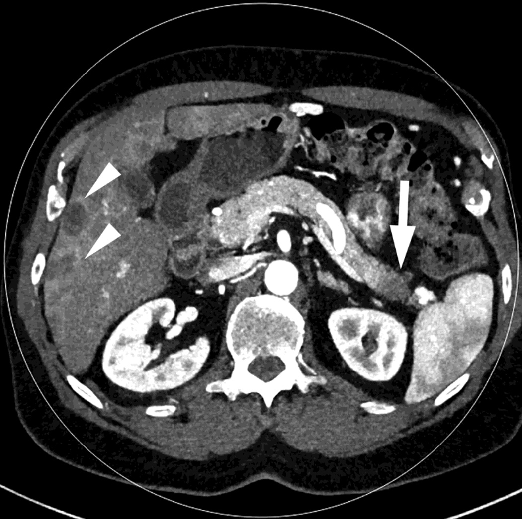
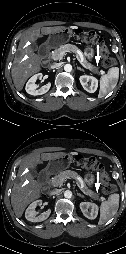
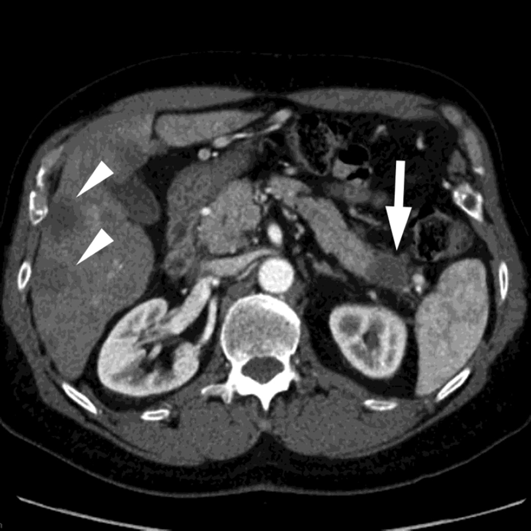
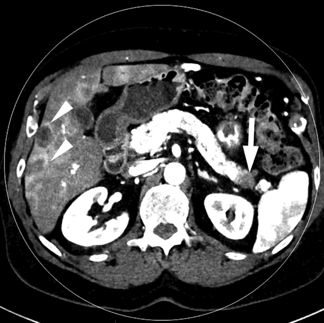
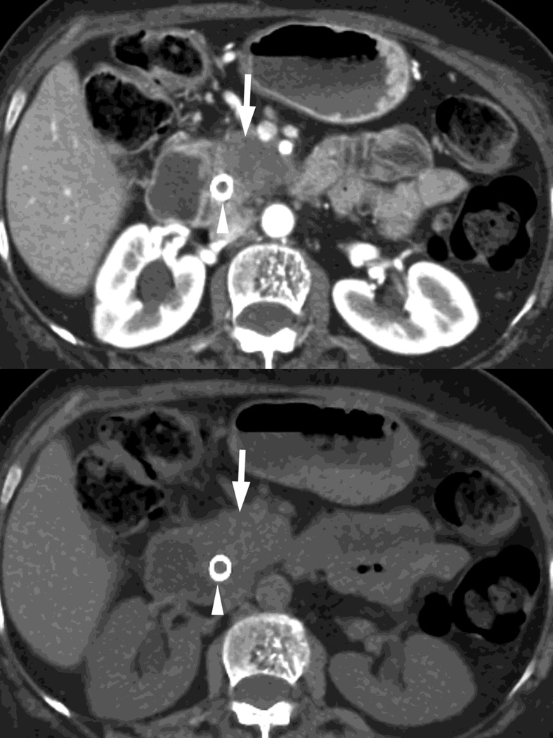
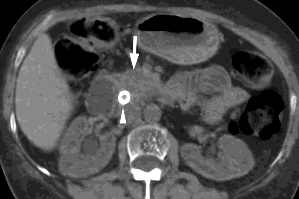
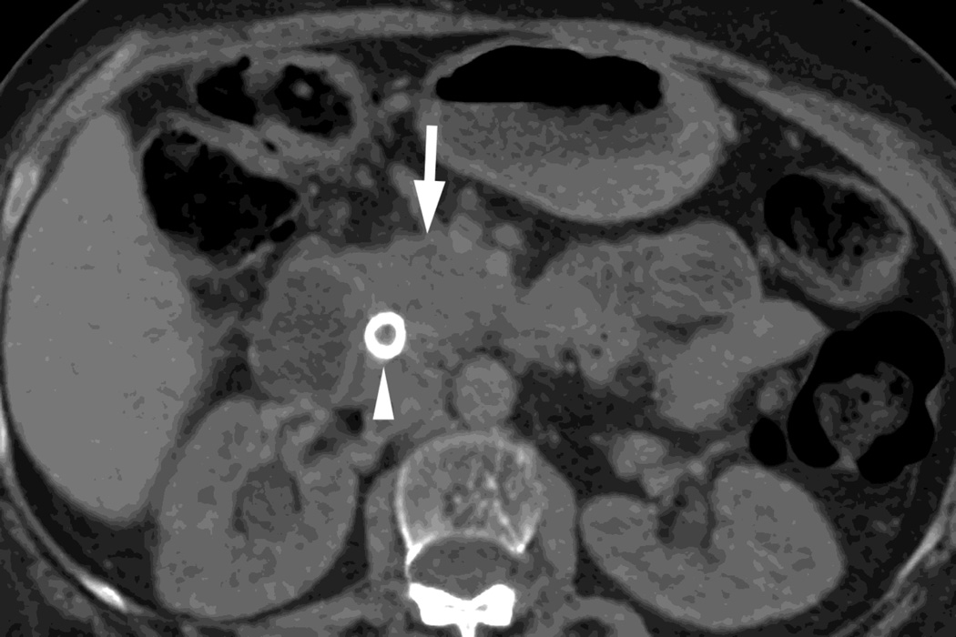
Dual-energy CT imaging has many potential uses in abdominal imaging. It also has unique requirements for protocol creation depending on the dual-energy scanning technique that is being utilized. It also generates several new types of images which can increase the complexity of image creation and image interpretation. The purpose of this article is to review, for rapid switching and dual-source dual-energy platforms, methods for creating dual-energy protocols, different approaches for efficiently creating dual-energy images, and an approach to navigating and using dual-energy images at the reading station all using the example of a pancreatic multiphasic protocol. It will also review the three most commonly used types of dual-energy images: "workhorse" 120kVp surrogate images (including blended polychromatic and 70 keV monochromatic), high contrast images (e.g., low energy monochromatic and iodine material decomposition images), and virtual unenhanced images. Recent developments, such as the ability to create automatically on the scanner the most common dual-energy images types, namely new "Mono+" images for the DSDECT (dual-source dual-energy CT) platform will also be addressed. Finally, an approach to image interpretation using automated "hanging protocols" will also be covered. Successful dual-energy implementation in a high volume practice requires careful attention to each of these steps of scanning, image creation, and image interpretation.

Keywords: Computed tomography; Dual-energy; Workflow.


Conflict of interest statement

Eric P. Tamm, Conflict of Interest: General Electric healthcare “in kind” research support.

Dianna D. Cody, Conflict of Interest: General Electric healthcare “in kind” research support. Philips Healthcare scientific advisory board. ACR CT accreditation reviewer.

Figures

Fig. 1
Fig. 1
Polychromatic blended images from dual source dual energy (DSDECT) (A–C) and rapid switching dual energy scans (RSDECT) (D) same patient, pancreatic tail ductal adenocarcinoma, same windowing, scans obtained 2 months apart. The DSDECT platform can create polychromatic energy images from variably "blending" data from the low (here 100kVp) and 140kVp data, with examples as shown, A) low energy (closer to 100kVp), B) mid (120kVp) and C) high (e.g. 140kVp). Low energy images emphasize contrast enhancement. Pancreatic cancer tumor (white arrow) and liver metastases (white arrowheads) are more conspicuous on the low energy images. The dotted circle indicates the area covered by dual energy imaging. Imaging outside of the circle is based solely on data from a single energy (here 100kVp). In contrast, the RSDECT scanner provides a polychromatic "quality control" series D), not meant for interpretation, and based solely on the 140kVp polychromatic data. We have nevertheless found this series useful as an adjunct for interpretation.
Fig. 1
Fig. 1
Polychromatic blended images from dual source dual energy (DSDECT) (A–C) and rapid switching dual energy scans (RSDECT) (D) same patient, pancreatic tail ductal adenocarcinoma, same windowing, scans obtained 2 months apart. The DSDECT platform can create polychromatic energy images from variably "blending" data from the low (here 100kVp) and 140kVp data, with examples as shown, A) low energy (closer to 100kVp), B) mid (120kVp) and C) high (e.g. 140kVp). Low energy images emphasize contrast enhancement. Pancreatic cancer tumor (white arrow) and liver metastases (white arrowheads) are more conspicuous on the low energy images. The dotted circle indicates the area covered by dual energy imaging. Imaging outside of the circle is based solely on data from a single energy (here 100kVp). In contrast, the RSDECT scanner provides a polychromatic "quality control" series D), not meant for interpretation, and based solely on the 140kVp polychromatic data. We have nevertheless found this series useful as an adjunct for interpretation.
Fig. 2
Fig. 2
Monochromatic energy images from same patient, imaged 2 months apart, as in Figure 1, for DSDECT, "Mono + algorithm," (A–C) and RSDECT (D–F) at 50 kev (A,D), 70 kev (B,E), and 140 keV (C,F). Images are all at the same window setting. Pancreatic tail tumor (white arrow) and liver metastases (white arrowheads). Enhancement becomes more conspicuous at lower keV. Note the difference in enhancement between the pancreatic tail tumor and adjacent pancreas..
Fig. 2
Fig. 2
Monochromatic energy images from same patient, imaged 2 months apart, as in Figure 1, for DSDECT, "Mono + algorithm," (A–C) and RSDECT (D–F) at 50 kev (A,D), 70 kev (B,E), and 140 keV (C,F). Images are all at the same window setting. Pancreatic tail tumor (white arrow) and liver metastases (white arrowheads). Enhancement becomes more conspicuous at lower keV. Note the difference in enhancement between the pancreatic tail tumor and adjacent pancreas..
Fig. 3
Fig. 3
Patient with small islet cell tumor (white arrow) imaged on the RSDECT platform that is seen on A) iodine-water, or iodine(-water), material density image, but not on the B) water-iodine, or water(-iodine) image confirming an enhancing lesion. The values within the voxels of this pair of images are actually calculated values of the density needed of the combination of water (on the water-iodine image) and iodine (as seen on the iodine-water image) needed to mimic the actual behavior at that voxel as measured at 80 and 140 kVp, The water image is utilized as a virtual noncontrast image, and the iodine image is utilized as a high contrast series to maximize the conspicuity of differences in contrast enhancement.
Fig. 3
Fig. 3
Patient with small islet cell tumor (white arrow) imaged on the RSDECT platform that is seen on A) iodine-water, or iodine(-water), material density image, but not on the B) water-iodine, or water(-iodine) image confirming an enhancing lesion. The values within the voxels of this pair of images are actually calculated values of the density needed of the combination of water (on the water-iodine image) and iodine (as seen on the iodine-water image) needed to mimic the actual behavior at that voxel as measured at 80 and 140 kVp, The water image is utilized as a virtual noncontrast image, and the iodine image is utilized as a high contrast series to maximize the conspicuity of differences in contrast enhancement.
Fig. 4
Fig. 4
Patient with recurrent pancreatic cancer that has metastasized (white arrowheads) to the liver. The DSDECT platform utilizes three material decomposition (iodine, fat and soft tissue) in the creation of A) virtual unenhanced and B) iodine material decomposition images. Measurements of the values from the virtual unenhanced image yield Hounsfield values.
Fig. 4
Fig. 4
Patient with recurrent pancreatic cancer that has metastasized (white arrowheads) to the liver. The DSDECT platform utilizes three material decomposition (iodine, fat and soft tissue) in the creation of A) virtual unenhanced and B) iodine material decomposition images. Measurements of the values from the virtual unenhanced image yield Hounsfield values.
Fig. 5
Fig. 5
DSDECT, pancreatic parenchymal phase of patient, status post Whipple procedure without recurrence, with A) 100–120kVp blended equivalent polychromatic, B) true precontrast and C) virtual noncontrast images.
Fig. 5
Fig. 5
DSDECT, pancreatic parenchymal phase of patient, status post Whipple procedure without recurrence, with A) 100–120kVp blended equivalent polychromatic, B) true precontrast and C) virtual noncontrast images.
Fig. 6
Fig. 6
RSDECT scan, pancreatic parenchymal phase of patient with pancreatic head ductal adenocarcinoma (white arrow) as seen on A)70keV monochromatic B) true precontrast, C) water-iodine or water(-iodine), and D) material suppressed iodine (MSI). The water(-iodine) yields measurements in calculated density, while an ROI on the MSI image would provide calculated Hounsfield units. Note the appearance of the renal cortex on the virtual noncontrast images versus the true precontrast image. A metallic common bile duct stent is present within the pancreatic head (white arrowhead)
Fig. 6
Fig. 6
RSDECT scan, pancreatic parenchymal phase of patient with pancreatic head ductal adenocarcinoma (white arrow) as seen on A)70keV monochromatic B) true precontrast, C) water-iodine or water(-iodine), and D) material suppressed iodine (MSI). The water(-iodine) yields measurements in calculated density, while an ROI on the MSI image would provide calculated Hounsfield units. Note the appearance of the renal cortex on the virtual noncontrast images versus the true precontrast image. A metallic common bile duct stent is present within the pancreatic head (white arrowhead)
Fig. 7
Fig. 7
Patient with small pancreatic body adenocarcinoma (white arrow) and liver metastases (white arrowheads) with examples of overview "workhorse" 100–120kVp equivalent, and high contrast series, for RSDECT, A) 70keV "workhorse", and high contrast B) 50 keV and C) iodine (water) material density image, and for DSDECT (here obtained 3months later), D) "workhorse" blended 100–120kVp polychromatic blend and high contrast E) 50keV and F) iodine material decomposition images. The near 120kVp equivalent image is used for most of the process of interpretation, with one or the other of the high contrast series utilized to facilitate identifying the primary tumor within the pancreas and its boundaries
Fig. 7
Fig. 7
Patient with small pancreatic body adenocarcinoma (white arrow) and liver metastases (white arrowheads) with examples of overview "workhorse" 100–120kVp equivalent, and high contrast series, for RSDECT, A) 70keV "workhorse", and high contrast B) 50 keV and C) iodine (water) material density image, and for DSDECT (here obtained 3months later), D) "workhorse" blended 100–120kVp polychromatic blend and high contrast E) 50keV and F) iodine material decomposition images. The near 120kVp equivalent image is used for most of the process of interpretation, with one or the other of the high contrast series utilized to facilitate identifying the primary tumor within the pancreas and its boundaries
Fig. 8
Fig. 8
An automated reading layout, or “hanging protocol,” for DSDECT (top row) and RSDECT (bottom row). Placed first is the 100–120kVp "workhorse" equivalent series (for the dual energy pancreatic parenchymal phase) and axial portal venous images (combined in the case of the RSDECT platform), followed by a high contrast series (50keV or iodine) and then portal venous multiplanar reconstructions. Coronal and portal venous phase, non-DECT are useful for evaluating for vascular involvement, and peritoneal disease, and are helpful for showing extent of disease at multidisciplinary conference. Lesser used series, such as localizer radiographs, dose injector information, radiation dose documentation, and thin section archival image series can be “pushed” to the end list of displayed series.

References

    1. Shuman WP, Green DE, Busey JM, et al. Dual-Energy Liver CT: Effect of Monochromatic Imaging on Lesion Detection, Conspicuity, and Contrast-to-Noise Ratio of Hypervascular Lesions on Late Arterial Phase. AJR Am J Roentgenol. 2014;203:601–606. - PubMed
    1. Patel BN, Thomas JV, Lockhart ME, et al. Single-source dual-energy spectral multidetector CT of pancreatic adenocarcinoma: optimization of energy level viewing significantly increases lesion contrast. Clin Radiol. 2013;68:148–154. - PubMed
    1. Bhosale P, Le O, Balachandran A, et al. Quantitative and Qualitative Comparison of Single-Source Dual-Energy Computed Tomography and 120-kVp Computed Tomography for the Assessment of Pancreatic Ductal Adenocarcinoma. J Comput Assist Tomogr. 2015;39:907–913. - PMC - PubMed
    1. Lin XZ, Wu ZY, Tao R, et al. Dual energy spectral CT imaging of insulinoma-Value in preoperative diagnosis compared with conventional multi-detector CT. Eur J Radiol. 2012;81:2487–2494. - PubMed
    1. Apfaltrer P, Sudarski S, Schneider D, et al. Value of monoenergetic low-kV dual energy CT datasets for improved image quality of CT pulmonary angiography. Eur J Radiol. 2014;83:322–328. - PubMed

MeSH terms