. 2016 Nov;19(9):516-532.
doi: 10.1016/j.mattod.2016.02.020.

Artificial cells: from basic science to applications

Affiliations

Artificial cells: from basic science to applications

Can Xu et al. Mater Today (Kidlington). 2016 Nov.

Abstract

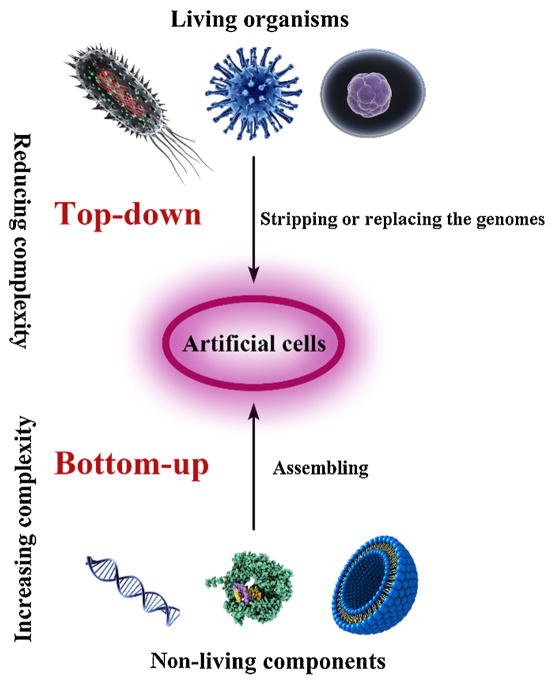
Artificial cells have attracted much attention as substitutes for natural cells. There are many different forms of artificial cells with many different definitions. They can be integral biological cell imitators with cell-like structures and exhibit some of the key characteristics of living cells. Alternatively, they can be engineered materials that only mimic some of the properties of cells, such as surface characteristics, shapes, morphology, or a few specific functions. These artificial cells can have applications in many fields from medicine to environment, and may be useful in constructing the theory of the origin of life. However, even the simplest unicellular organisms are extremely complex and synthesis of living artificial cells from inanimate components seems very daunting. Nevertheless, recent progress in the formulation of artificial cells ranging from simple protocells and synthetic cells to cell-mimic particles, suggests that the construction of living life is now not an unrealistic goal. This review aims to provide a comprehensive summary of the latest developments in the construction and application of artificial cells, as well as highlight the current problems, limitations, challenges and opportunities in this field.


Figures

FIGURE 1
FIGURE 1
Approaches for the design and construction of artificial cells: In the top-down approach, artificial cells are created by stripping or replacing the genomes of living organisms (cells, bacteria or viruses), reducing their complexity, and only retaining minimum substances to maintain the essential life. In the bottom-up approach, artificial cells are constructed by assembling non-living components to form an integral that can replicate essential properties of natural cells.
FIGURE 2
FIGURE 2
(a) Images of (I) M. mycoides JCVI-syn1.0 (synthesized cells) and (II) wild-type (WT) M. mycoides: The two cell colonies display similar fried egg-like morphology. The blue color of JCVI-syn1.0 colonies is due to X-gal staining. The WT cells do not contain the lacZ gene and hence no blue color. (b) TEM images of (I) M. mycoides JCVI-syn1.0 and (II) WT M. mycoides. The two cell colonies show similar ovoid morphology [13]. Copyright © 2010, The American Association for the Advancement of Science.
FIGURE 3
FIGURE 3
(a) Illustration of the working principle of sugar-producing protocells. The formose reaction is carried out inside a lipid vesicle, which is driven by the increased pH outside (top left). The product, carbohydrate–borate, is formed and diffuses from the vesicle into the medium (top right). The diffused products are then detected by the bacterium V. harveyi and bind to LuxP/LuxQ signal transduction protein, resulting in a protein phosphorylation response and the subsequent expression of the luxCDABE gene (bottom right) with detectable bioluminescence (bottom left) [58]. Copyright © 2009, Nature Publishing Group. (b) Artificial cells translate chemical signals for E. coli. The molecule theophylline cannot be detected by E. coli (top). Through the artificial cell system, theophylline can be translated into isopropyl β-D-1-thiogalactopyranoside (IPTG), which can be sensed by E. coli and induce its response (bottom) [59]. Copyright © 2014, Nature Publishing Group.
FIGURE 4
FIGURE 4
Modes of vesicle growth and division. Vesicle growth can occur by incorporation of fatty acid monomers, micelles or other vesicles. The size of the vesicle will increase and the vesicle may divide into smaller vesicles spontaneously due to the thermodynamic instability [6]. Copyright © 2001, Nature Publishing Group.
FIGURE 5
FIGURE 5
Schematic diagram of cyclic multilamellar vesicle growth and division. After being fed with micelles, the fatty acid vesicles grow in size. Because of the transient imbalance between surface area and volume growth, the initial spherical morphology eventually turns into long thread-like shapes. Then the thread-like vesicles divide into multiple daughter vesicles due to the shear stress [78]. Copyright © 2009 American Chemical Society.
FIGURE 6
FIGURE 6
(a) Illustration of Mg2+ responsive protocell. Mg2+ dependent ribozyme molecules are encapsulated inside fatty acid vesicles. By adding external Mg2+, the ribozymes can be activated and catalyzed RNA replication [80]. Copyright © 2005, American Chemical Society. (b) Clay-catalyzed protocell model. Nomarski optics images (I and III) and fluorescence images (II and IV) of clay-catalyzed fatty acid vesicles. (I and II) Negatively charged alumino-silicate ceramic microspheres (Zeeospheres) catalyze the formation of myristoleate vesicles. Arrowheads indicate Zeeospheres. (III and IV) Natural montmorillonite clay particles catalyze the formation of myristoleate vesicles [81]. Copyright ©2003, the American Association for the Advancement of Science. (c) The amplification of encapsulated DNA combines with self-reproduction of giant vesicles (GVs). (I) Illustration of the chemical link between amplification of DNA and self-reproduction of GVs. The amplification of DNA can be carried out within GVs. The amplified DNA can adhere to the inner leaflet of the GV, accelerating the self-reproduction of GV due to the imbalance between the inner and outer leaflets. (II) Real-time observation of morphological changes of DNA-amplified GVs after addition of membrane precursor (V*) [82]. Copyright ©2011, Nature Publishing Group.
FIGURE 7
FIGURE 7
The procedures for preparation of proteinosomes. (a) The temperature sensitive polymer PNIPAAm is grafted onto the protein BSA via a mercaptothiazoline-amine reaction to form protein-polymer conjugates. (b) The conjugates self-assemble into vesicles in the Pickering emulsion. After removing the oil phase, the membrane of the proteinosome is cross-linked using PEG-bis(N-succinimidyl succinate) into a continuous membrane [88]. Copyright © 2013, Nature Publishing Group.
FIGURE 8
FIGURE 8
Various biologically active materials can be encapsulated in semipermeable polymer-based artificial cells, individually or in combination [90]. The semipermeable membrane can protect these materials from being degraded or affected by external environment and prevent them from leaking out to contaminate the body fluids. The membrane has a selective permeability to small substrate molecules and can also release products to the environment. Copyright © 2005, Nature Publishing Group.
FIGURE 9
FIGURE 9
(a) Optical micrographs and (b) TEM image of polylysine–ATP droplets. (c) Scheme summarizing the properties of peptide/mononucleotide microdroplets relevant to their use as membrane-free protocell models (ε = dielectric constant). The microdroplets selectively sequester porphyrins, inorganic nanoparticles, and enzymes to generate supramolecular stacked arrays of light-harvesting molecules, nanoparticle-mediated oxidase activity, and enhanced rates of glucose phosphorylation, respectively [118]. Copyright © 2011, Nature Publishing Group.
FIGURE 10
FIGURE 10
Schematic of the preparation process of the RBC-membrane-coated PLGA nanoparticles (NPs). After hypotonic treatment and extrusion, the RBC membranes can be separated from the cells. These membranes are incubated with NPs. RBC membrane camouflaged NPs can be obtained following extrusion [131]. Copyright © 2011, by the National Academy of Sciences.
FIGURE 11
FIGURE 11
(a) (I) Preparation of RBC-shaped particles from hollow polystyrene (PS) templates: Proteins and polyelectrolytes are deposited onto the template surface using layer-by-layer (LBL) technique, followed by cross-linking of the layers to increase stability. PS cores are dissolved by an organic solvent to yield RBC-shaped soft materials. Proteins, drugs or contrast agents can be loaded inside the particles. (II) Preparation of biocompatible RBC-mimicking particles from PLGA templates: RBC-shaped PLGA templates are synthesized by electrohydrodynamic jetting technology. Protein layers are then coated on the template by the LBL method. After the dissolution of the template core, RBC-shaped biocompatible materials are obtained. (III) SEM image of RBC-mimicking particles prepared from PLGA template by LbL deposition of PAH/BSA and subsequent dissolution of the polymer core [142]. Copyright © 2009, by the National Academy of Sciences. (b) (I) RBC-shaped PEG particles prepared by an all polydimethylsiloxane (PDMS) microfluidic channel with a height of 4.5 mm using the stop flow lithography (SFL) technique. (II) Microscope images of RBC-shaped PEG colloids [143]. Copyright © 2009, WILEY-VCH Verlag GmbH & Co. KGaA, Weinheim. (c) RBC mimetic hydrogel particles prepared by the particle replication through the nonwetting template (PRINT) technique. (Left) Illustration for the PRINT process. The pre-hydrogel mixture (red), composed of 2-hydroxyethyl acrylate (HEA), poly (ethylene glycol) diacrylate, a photoinitiator, and polymerizable fluorescent dyes, is implanted in the disk-shaped wells of an elastomeric fluoropolymer mold (green). The mold is peeled away at a pressured nip (black), wicking away the excess liquid. Then the filled mold is exposed to UV light to irradiate the cross-linking of the hydrogel. After removing the mold by freezing onto a thin film of 1% poly (vinyl alcohol) in water (blue), the RBC-shaped hydrogel particles are obtained. (Right) Fluorescent images of (Top) 10% cross-linked, (Bottom) 2% cross-linked RBC shaped hydrogel. Scale bars are 20 μm [144]. Copyright © 2011, by the National Academy of Sciences.
FIGURE 12
FIGURE 12
(a) Capturing the morphology of mammalian cells by silica: (I) Illustrations of cell silicification process, (II) Images of AsPC-1 pancreatic carcinoma cells during the silicification process, (i, ii) Images of hydrated cells, (iii, iv) Images of dehydrated composites and silica replicas, (Insets) Energy dispersive spectroscopy description of cells [150], Copyright © 2012, by the National Academy of Sciences. (b) Construction of smart mesoporous silica particles (MSPs) with cell-capturing capacity by using macrophage as a template: (I) Illustrations of the shape and morphology of macrophage by using silica and magnetic particles, (II) (i) SEM image of a pristine macrophage, (ii) TEM image of citrate-coated superparamagnetic iron oxide nanoparticles (SPIONs), (iii) TEM image of a macrophage with endocytosed SPIONs, (Inset) Higher magnification view of internalized SPIONs, Scale bar: 100 nm. (iv) SEM image of the MSP that replicated the morphology of a macrophage, (III) Illustration of modification steps of smart particles: There is a cleavable disulfide bond linker between antibody (anti-EpCAM) and the particle [151]. Copyright © 2014 WILEY-VCH Verlag GmbH & Co. KGaA, Weinheim.
FIGURE 13
FIGURE 13
Preparation and structure of the VM-nanogel: Hydrophobic polymer, poly (l-histidine-co-phenylalanine) (poly (His32-co-Phe6)), is used to form the core of the VM-nanogel. Anticancer drug, doxorubicin (DOX) is loaded inside. PEG forms the inner shell by linking onto the polymer core. The free end of the other side of PEG is linked to BSA, resulting in a capsid-like hydrophilic protein outer shell. The resulting nanogel has a diameter of about 55 nm under pH 7.4. When the pH is decreased to 6.4, the diameter of the nanogel is spontaneously increased to 355 nm [152]. Copyright © 2008 WILEY-VCH Verlag GmbH & Co. KGaA, Weinheim.

References

    1. Masters BR. eLS. John Wiley & Sons, Ltd; 2001.
    1. Garrett WS. J Cell Biol. 2015;210(1):7. - PMC - PubMed
    1. Pohorille A, et al. Trends Biotechnol. 2002;20(3):123. - PubMed
    1. Ding Y, et al. Life. 2014;4(4):1092. - PMC - PubMed
    1. Saraniti M. Nat Nanotechnol. 2008;3(11):647. - PubMed

LinkOut - more resources