Review
. 2017 May 15:91:588-605.
doi: 10.1016/j.bios.2016.12.062. Epub 2016 Dec 30.

Microfluidic approaches for isolation, detection, and characterization of extracellular vesicles: Current status and future directions

Affiliations
Review

Microfluidic approaches for isolation, detection, and characterization of extracellular vesicles: Current status and future directions

Shima Gholizadeh et al. Biosens Bioelectron. .

Abstract

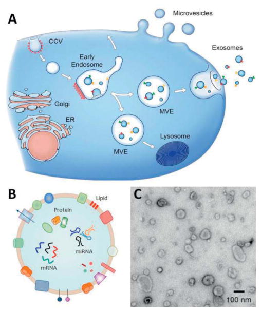
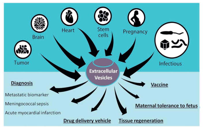
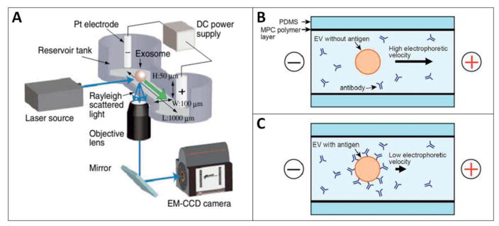
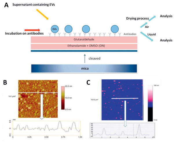
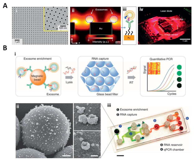
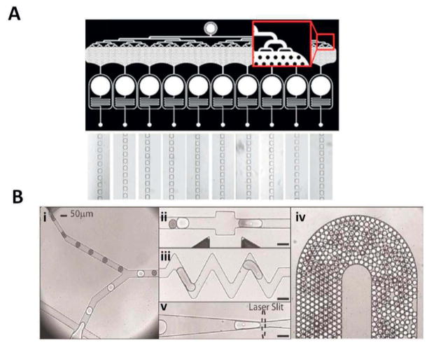
Extracellular vesicles (EVs) are cell-derived vesicles present in body fluids that play an essential role in various cellular processes, such as intercellular communication, inflammation, cellular homeostasis, survival, transport, and regeneration. Their isolation and analysis from body fluids have a great clinical potential to provide information on a variety of disease states such as cancer, cardiovascular complications and inflammatory disorders. Despite increasing scientific and clinical interest in this field, there are still no standardized procedures available for the purification, detection, and characterization of EVs. Advances in microfluidics allow for chemical sampling with increasingly high spatial resolution and under precise manipulation down to single molecule level. In this review, our objective is to give a brief overview on the working principle and examples of the isolation and detection methods with the potential to be used for extracellular vesicles. This review will also highlight the integrated on-chip systems for isolation and characterization of EVs.

Keywords: Exosomes; Extracellular vesicles; Microchip; Microfluidics.


Figures

Figure 1
Figure 1
(A) Schematic representation of biogenesis and release of EVs from cells. Direct budding produces MVs through the plasma membrane. Exosomes are formed initially as intraluminal vesicles (ILVs) by growing into endosomes and multivesicular endosomes (MVEs). They are later released through the fusion of MVEs with the plasma membrane. Arrows show the transport direction of proteins and lipids between organelles, MVEs, and plasma membrane for exosome secretion. Adapted with permission from ref (EL Andaloussi 2013). Copyright 2013, the Rockefeller University Press. (B) Schematic representation indicates the detailed structure EVs. EV is composed of a lipid-based bilayer that contains different transmembrane proteins, essential for transport, and cell targeting. Other proteins that are involved in biogenesis from endosome or plasma membrane together with genetic materials, which can be used as molecular markers for the detection of exosomes. Adapted with permission from ref [web_evpedia]. (C) A transmission electron microscopy image of extracellular vesicles extracted from human urine. Adapted with permission from ref [web_vdpol].
Figure 2
Figure 2
Applications of extracellular vesicles (EVs) in normal and pathological conditions. Adapted with permission from ref (De Toro 2015). Copyright 2015, Frontiers.
Figure 3
Figure 3
Heterogeneous EVs populations separated using microfluidic systems based on their intrinsic (passive) and extrinsic (dynamic) characteristics. (A) Dielectrophoresis (DEP)-based approach in which EVs are exposed to a non-uniform electric field and EVs are separated based on the difference between the DEP (FDEP) and (Fgrav) gravitational forces. (B) The hydrodynamic-based method that utilizes the competing hydrodynamic wall lift force (FL) and a shear gradient lift force (FS). (C) The immunoaffinity-based technique that depend on the interaction of cell surface molecules (red) with antibodies or other ligands (blue) functionalized on the channel surface. (D) Magnetic-based technique: an applied magnetic field is used to deflect and focus cells labeled with magnetic particles (green). Adapted with permission from ref (Jackson 2013), Copyright 2013, Elsevier.
Figure 4
Figure 4
(A) Schematic representation of microcapillary electrophoresis (μCE system) on-chip integrated with a laser dark-field microscope. The system composed of different compartments such as electrodes, power supply, a 488-nm laser source, an electron multiplying charge-coupled device (EM-CCD) camera, and an inverted microscope (Nikon Ti-U). Adapted with permission from ref (Akagi 2014). Copyright 2014, IOP Science. (B, C) Schematic diagram of immuno-electrophoresis of EVs without and with antigen respectively on a μCE chip. Changes in zeta potential and electrophoretic mobility correlates with the immunoreactivity of individual EVs since the surface charge of the EV are modified upon antibody binding. The 2-methacryloyloxyethyl phosphorylcholine (MPC) polymer was applied to coat the inner surface of the flow channel to prevent electro-osmotic flow or non-specific adsorption of EVs. Adapted with permission from ref (Akagi 2015). Copyright 2015, PLOS ONE.
Figure 5
Figure 5
(A) Schematic illustration of mica surface functionalization for AFM analyses in the air and liquid modes. (B) Air mode based cross-section image of the extracellular vesicles (EVs) derived from breast cancer cells using surface modified with anti-tissue factor (TF) antibodies. Image size: 1×1μm2. (C) Liquid mode based cross-section image of the same type EVs, using surface modified with TF. Image size: 3×3μm2. The colorimetric scale indicates the Z-dimension. Adapted with permission from ref (Hardij 2013). Copyright 2013, Co-Action Publishing.
Figure 6
Figure 6
(A) Schematic representation of the Nanosight design. (B) A snapshot from a video taken by Nanosight. Each white spot is one nanoparticle dispersed in a liquid medium. (C) Brownian motion pattern of single nanoparticle traced by NTA software. Adapted with permission from ref (Carr 2013). Copyright 2013, Malvern Instruments Ltd.
Figure 7
Figure 7
Electrochemical detection of EVs. (A) The design of an 8-channel microfluidic device showing the microchannel cross-section with inlets, outlets, and the working electrodes. Adapted with permission from ref (Hoegger 2007). Copyright 2007, Springer. (B) Schematic of an aptamer-based exosome detection that includes a gold electrode array patterned and a flow chamber made in PDMS. The changes in electrochemical signal were proportional to the concentration of exosomes captured. Adapted with permission from ref (Zhou 2016). Copyright 2016, Elsevier.
Figure 8
Figure 8
Application of scanning ion occlusion spectroscopy for the detection of EVs. (A) qNano (a bench-top) instrument. Adapted with permission from ref [web_izon]. (B) A fluid cell, consisting of adjustable jaws, which are holding at the center, a tunable membrane composed of nanopores. (C) Schematic cross-section of pore, which depicts the principles of selective transport for a bimodal particle suspension. Adapted with permission from ref (Roberts 2010). Copyright 2010, John Wiley & Sons, Inc.
Figure 9
Figure 9
Application of nanopore gated electrical sensor combined with optical detection in a microfluidic platform. (A) Schematic view on particle movement through the nanopore gate. Liquid flow direction shown with blue arrow. Red area demonstrates the optical excitation volume. (B) Movement of biological particle through electrically gated nanopore. (C) Two characteristic signals, electrical (black) and optical fluorescence (red), for separate detection events related to a single particle. The electrical current dip and the fluorescence spike appear separated due to time need for a particle to travel (flow) from the nanopore towards the optical excitation spot (Δt). (D) Computational cross-correlation of detection events (particles), adjusted for delay time (Δt). Adapted with permission from ref (Liu 2014). Copyright 2014, ACS.
Figure 10
Figure 10
(A) The first microfluidic device for the separation of microvesicles: (i) after flowing the serum samples through the microchannels at optimized flow rates, microvesicles attached to the surface, and later fixed for SEM or lysed for RNA extraction. Adapted with permission from ref (Chen 2010). Copyright 2010, Royal Society of Chemistry; (ii) purified blood plasma sample run over antibody coated mica surface on PDMS chip; (iii) followed by removal of mica surface and imaging with AFM analysis. Adapted with permission from ref (Ashcroft 2012). Copyright 2012, Springer Link. (B) Miniaturized nuclear magnetic resonance (μNMR) system, consisting microchannels for sample manipulations, integrated with a portable magnet for magnetic field generation, micro coil array, and miniaturized electronics. Adapted with permission from ref (Lee 2008). Copyright 2008, Nature Publishing Group. (C) A microfluidic prototype comprised of multiple microchannels for the immunomagnetic capture of circulating exosomes, on-chip lysis, and characterization. Ports 1–4 show the inlet junctions for (in order): beads for exosome capture, washing/lysis buffer, beads for protein capture, ELISA reagents. Adapted with permission from ref (He 2014). Copyright 2014, Royal Society of Chemistry.
Figure 11
Figure 11
(A) An SEM micrograph of nanoholes in the nPLEX sensor: (i) the structure was embedded in a 200 nm thick gold film, placed on a glass substrate. The inset is a zoomed image; (ii) Enhancement of the electromagnetic field strength, limited to the nanohole surface. An increased in detection sensitivity is determined which is due to the overlap of electromagnetic filed with the size of captured exosomes at nanohole surface; (iii) a schematic representation of polyethylene glycol (PEG) coated gold surface for conjugation with exosome specific antibodies on top; (iv) A prototype nano-plasmonic sensor integrated with miniaturized imaging system. Adapted with permission from ref (Im 2014). Copyright 2014, Nature Publishing Group. (B) Antibody coated magnetic beads applied for cancer exosome capture and enrichment: (i) exosomes capturing and lysis. The extracted RNA in the flow channels are captured (adsorbed) via a passing through a filter composed of packed glass beads. Next the RNA is collected (eluted) and RT-PCR is applied (on-chip) for quantitation; (ii) SEM images of antibody-functionalized magnetic microbeads after exosome capture. Microbeads (left, 3 μm) functionalized with affinity ligands; (iii) A prototype of iMER system. The microfluidic chamber was engineered to integrate all the processing components for multiplexed detection. Scale bar, 1 cm. Adapted with permission from ref (Shao 2015). Copyright 2015, Nature Publishing Group.
Figure 12
Figure 12
(A) Ultra-high-throughput and small droplets production system, which allows the production (up to 110,000 droplets/s) of highly monodisperse droplets (channel width: 100 μm). Adapted with permission from ref (Lim 2015). Copyright 2015, AIP Publishing. (B) Droplet-based microfluidic platform composed of 5 integrated modules for high-throughput cell viability assay: (i) a set of 2 nozzles with Y junction which enables mixing of the streams via alternating one droplet type with another type (interdigitation); (ii) a fusion module that delivered an (alternating current) AC field permitted, which enables electrically-controlled merging of pairs of droplets (100 μm deep); (iii) a mixing module that is used for enhancing droplets mixing in a shorter time frame (100 μm deep); (iv) a delay line module that is utilized for incubation (15 min) of droplets to stain the cells on-chip (260 μm deep); (v) a detection module that is used for trapping droplets vertically and laterally to excite them with a laser for the fluorescent signals collection (100μm deep). Adapted with permission from ref (Brouzes 2009). Copyright 2009, PubMed Central.

Similar articles

Cited by

References

    1. [web_evpedia] (http://evpedia.info)

    1. [web_izon] (http://www.izon.com/products/qnano/)

    1. [web_vdpol] (http://www.edwinvanderpol.com)

    1. Agarwal AFG, Letizia M, Tung SL, Boardman D, Lechler R, Lombardi G, Smyth LA. Front Immunol. 2014;5:555. - PMC - PubMed
    1. Ahn K, Kerbage C, Hunt TP, Westervelt RM, Link DR, Weitz DA. Appl Phys Lett. 2006;88:264105.

MeSH terms