Review
. 2016 Dec;6(6):772-784.
doi: 10.21037/qims.2016.12.04.

Classifying thoracolumbar fractures: role of quantitative imaging

Affiliations
Review

Classifying thoracolumbar fractures: role of quantitative imaging

Fernando Ruiz Santiago et al. Quant Imaging Med Surg. 2016 Dec.

Abstract

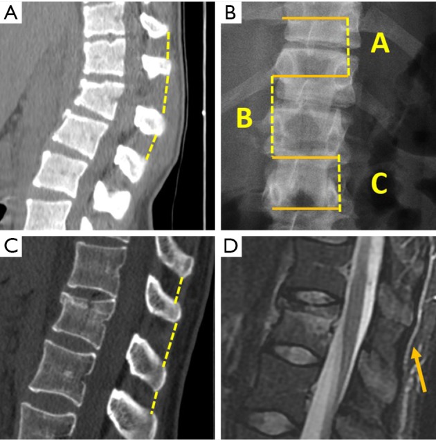
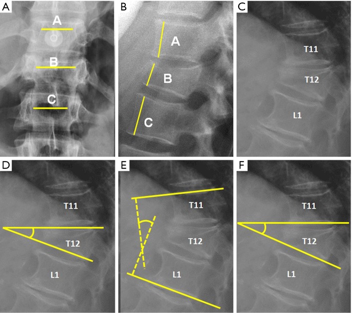
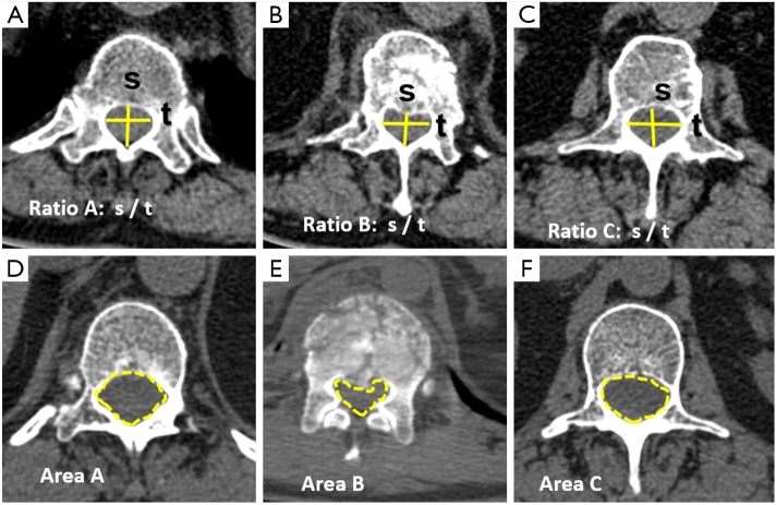
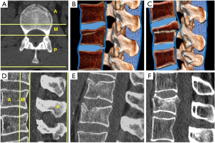
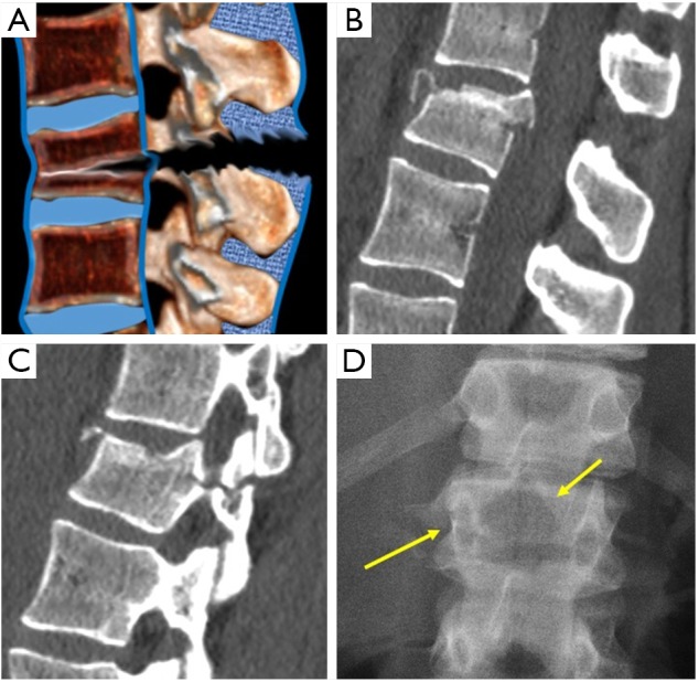
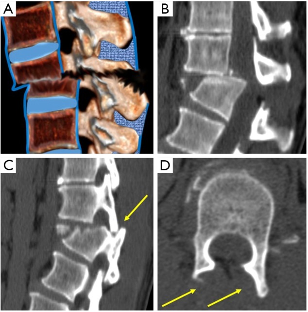
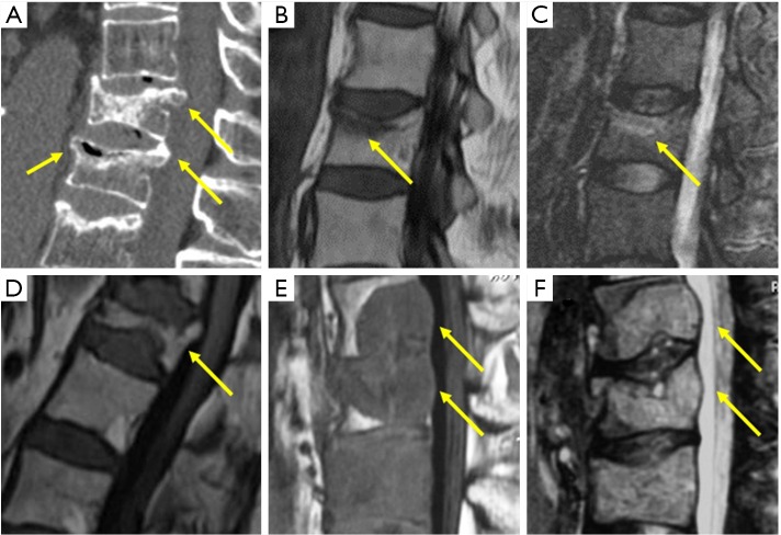
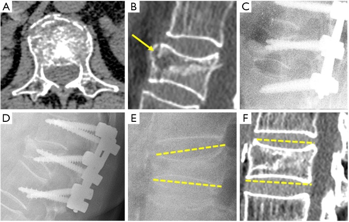
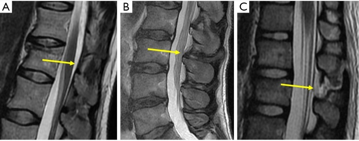
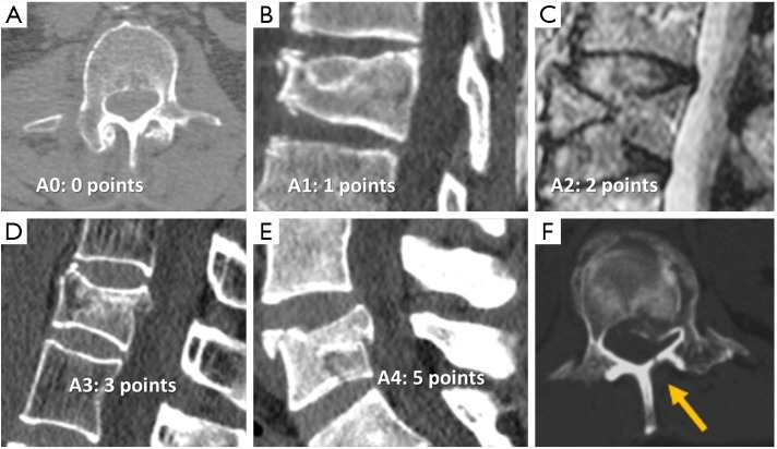
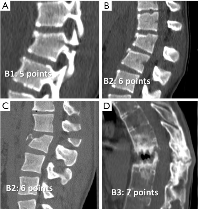
This article describes different types of vertebral fractures that affect the thoracolumbar spine and the most relevant contributions of the different classification systems to vertebral fracture management. The vertebral fractures types are based on the three columns model of Denis that includes compression, burst, flexion-distraction and fracture-dislocation types. The most recent classifications systems of these types of fractures are reviewed, including the Thoracolumbar Injury Classification and Severity score (TLICS) and the Arbeitsgemeinschaft für Osteosynthesefragen Spine Thoracolumbar Injury Classification and Severity score (AOSpine-TLICS). Correct classification requires a quantitative imaging approach in which several measurements determine TLICS or AOSpine-TLICS grade. If the TLICS score is greater than 4, or the AOSpine-TLICS is greater than 5, surgical management is indicated. In this review, the most important imaging findings and measurements on radiography, multidetector computed tomography (MDCT) and magnetic resonance imaging (MRI) are described. These include degree of vertebral wedging and percentage of vertebral height loss in compression fractures, degree of interpedicular distance widening and spinal canal stenosis in burst fractures, and the degree of vertebral translation or interspinous widening in more severe fractures types, such as flexion-distraction and fracture-dislocation. These findings and measurements are illustrated with schemes and cases of our archives in a didactic way.

Keywords: Vertebral fractures; computed tomography; plain radiography; spinal injuries; thoracolumbar trauma.


Conflict of interest statement

The authors have no conflicts of interest to declare.

Figures

Figure 1
Figure 1
Interspinous distance measurement. (A) Sagittal multiplanar reformat (MPR) from multidetector computed tomography (MDCT). The gap between the spinous processes is measured. A 14 mm interspinous widening is consistent with posterior ligamentous complex (PLC) tear. (B) interspinous distance is measured in AP radiographs by measuring the distance between the upper borders of the spinous processes projection of contiguous vertebrae. Percentage of widening of the interspinous distance can be calculated with the following formula, where A is the interspinous distance of the normal superior vertebra, B is the interspinous distance at the fractured vertebra and C is the interspinous distance of the normal inferior vertebra: % of widening = (B-(A+C)2)(A+C)2×100. (C) Sagittal MPR in MDCT shows 7 mm interspinous widening suspicious of PCL tear that was ruled out by MRI (arrow in D).
Figure 2
Figure 2
Radiological measurements in plain film radiography. (A) Interpedicular distance measured from the closest point of the medial aspect of both pedicles. Percentage of widening of the interpedicular distance can be calculated by the following formula, where A is the interpedicular distance of the normal superior vertebra, B is the interpedicular distance at the fractured vertebra and C is the interpedicular distance of the normal inferior vertebra: % of widening = (B-(A+C)2)(A+C)2×100; (B) Anterior vertebral height. The percentage of vertebral height loss can be calculated by the following formula, where A is the height of normal superior vertebra, B is the height of the fractured vertebral body and C is the height of normal inferior vertebra: % of vertebral height loss =((A+C)2-B)(A+C)2×100; (C) Wedge fracture of T12; (D) local Kyphosis is the angle between both endplates of fractured vertebra; (E) regional kyphosis is the angle between the upper endplate of the vertebra overlying the fractured vertebral body and the lower endplate of the vertebra underlying the fractured vertebral body; (F) segmental kyphosis (SK) is the angle between the inferior endplate of the injured vertebra and the inferior endplate of the overlying vertebra (segment = injured vertebra + overlying disc).
Figure 3
Figure 3
Radiological measurements with multidetector computed tomography (MDCT). (A-C) Sagittal to transverse diameter ratio decrease is compared with the ratio of the superior and inferior normal vertebrae; (D-F) the canal area decrease can be calculated by the following formula, where A is the canal area at the normal superior vertebral body, B is the canal area at the fractured vertebral body, and C is the canal area normal inferior vertebral body: % canal area decrease =((A+C)2-B)(A+C)2×100.
Figure 4
Figure 4
Three columns Denis’ model. (A) Axial scheme; (B) sagittal scheme of compression fracture; (C) sagittal scheme of burst fracture; (D) sagittal scheme of three columns Denis’ model; (E) sagittal CT of compression fracture; (F) sagittal CT of burst fracture.
Figure 5
Figure 5
Flexion-distraction fractures. (A) Sagittal scheme. (B) Sagittal CT showing interspinous widening and the horizontal fracture of the posterior arch (C). (D) Radiograph showing the empty body sign and the horizontal fracture of the pedicle (arrows).
Figure 6
Figure 6
Fracture-dislocation fractures. (A) Sagittal scheme; (B) sagittal CT of a fracture dislocation; (C) sagittal CT of locked facet (arrow); (D) axial CT showing naked facets (arrows).
Figure 7
Figure 7
(A) Sagittal MDCT with intravertebral cleft (anterior arrow) and retropulsed bone margins (posterior arrows). Sagittal T1 (B) and STIR (C) of band like edema in acute osteoporotic fracture. (D) Chronic osteoporotic fracture with vertebra deformity but normal marrow signal. Sagittal T1 (E) and STIR (F) of pathologic metastatic fractures with convex vertebral borders.
Figure 8
Figure 8
Short segment instrumentation failure. This patient suffered a L1 burst fracture and scored 8 on the load sharing classification system. Apposition of bone fragments: 3 (A); Vertebral body comminution: 3; an intra-vertebral cleft or cyst is also present (arrow) (B). Kyphotic correction: 2 (C). After several months kyphotic deformity increased (D). In another patient, local kyphosis changed from 15º in standing radiograph (E) to 0º in CT scan (F) and was diagnosed of unstable vertebral body fracture.
Figure 9
Figure 9
Injuries of the PLC. (A) Intact posterior ligament complex (arrow); (B) indeterminate injury (arrow); (C) complete injury (arrow).
Figure 10
Figure 10
Type A fractures of the Arbeitsgemeinschaft für Osteosynthesefragen Spine Thoracolumbar Injury Classification and Severity score (AOSpine-TLICS). (A) 0 fracture affects only the transverse or spinous processes of the spine; (B) A1 is a wedge compression fracture without involvement of posterior wall of the vertebral body; (C) A2 fracture is a pincer or split fracture of both endplates without involvement of the posterior vertebral body; (D) A3 is a burst fracture affecting a single endplate; (E) A4 fracture is a complete burst fracture affecting both endplates; (F) Sagittally oriented fractures of the lamina are typical for stable burst fractures.
Figure 11
Figure 11
Type B fractures of the Arbeitsgemeinschaft für Osteosynthesefragen Spine Thoracolumbar Injury Classification and Severity score (AOSpine-TLICS). (A) B1 is a monosegmental osseous injury with damage of the posterior tension band; (B) B2 fracture with ligamentous posterior tension band injury; (C) B2 fracture with bony posterior tension band injury; (D) B3 fracture is an anterior tension band injury. In this case, secondary to ankylosing spondylitis.

References

    1. Alpantaki K, Bano A, Pasku D, Mavrogenis AF, Papagelopoulos PJ, Sapkas GS, Korres DS, Katonis P. Thoracolumbar burst fractures: a systematic review of management. Orthopedics 2010;33:422-29. 10.3928/01477447-20100429-24 - DOI - PubMed
    1. DeWald RL. Burst fractures of the thoracic and lumbar spine. Clin Orthop Relat Res 1984;189:150-61. - PubMed
    1. Gertzbein SD. Scoliosis Research Society. Multicenter spine fracture study. Spine (Phila Pa 1976) 1992;17:528-40. 10.1097/00007632-199205000-00010 - DOI - PubMed
    1. Rajasekaran S, Kanna RM, Shetty AP. Management of thoracolumbar spine trauma: An overview. Indian J Orthop 2015;49:72-82. 10.4103/0019-5413.143914 - DOI - PMC - PubMed
    1. Kelly RP, Whitesides TE, Jr. Treatment of lumbodorsal fracture-dislocations. Ann Surg 1968;167:705-17. 10.1097/00000658-196805000-00009 - DOI - PMC - PubMed

LinkOut - more resources