Review
. 2017 Jan 24;6(1):5.
doi: 10.3390/biology6010005.

A Molecular View of Kinetochore Assembly and Function

Affiliations
Review

A Molecular View of Kinetochore Assembly and Function

Andrea Musacchio et al. Biology (Basel). .

Abstract

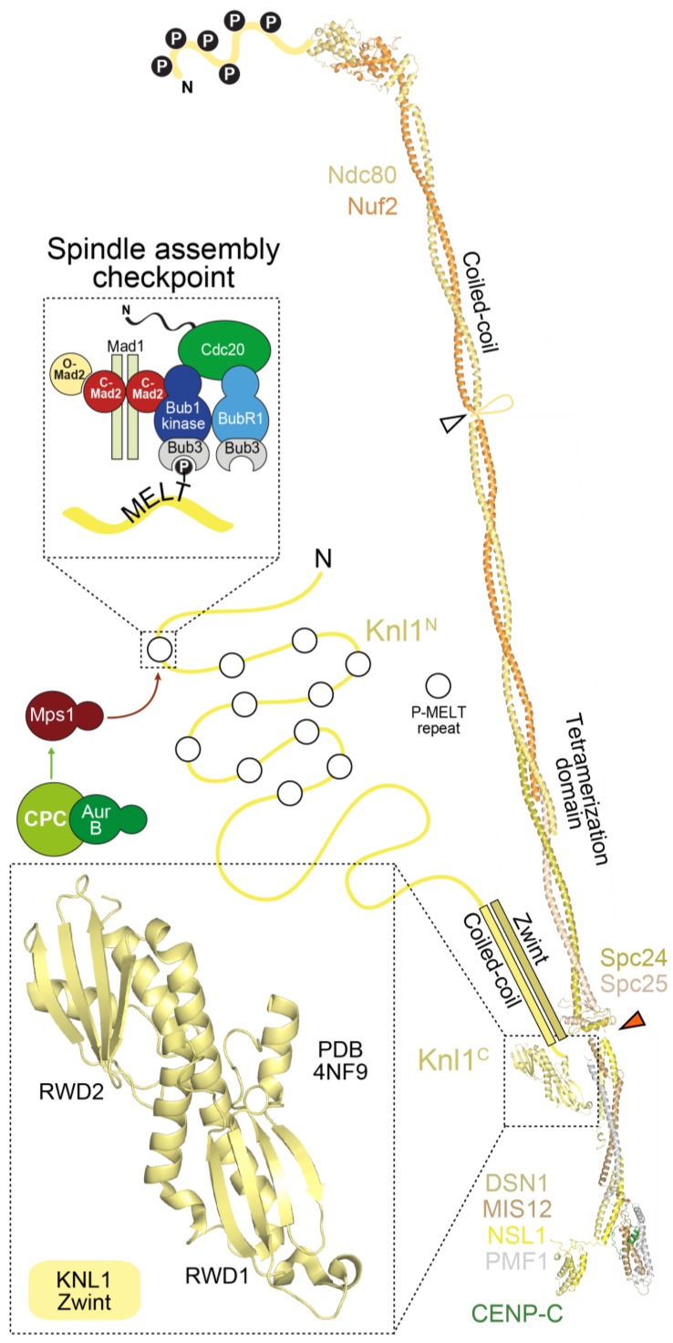
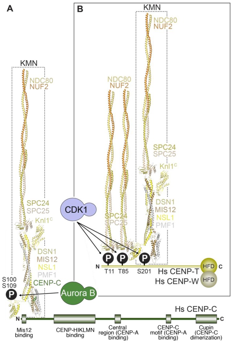
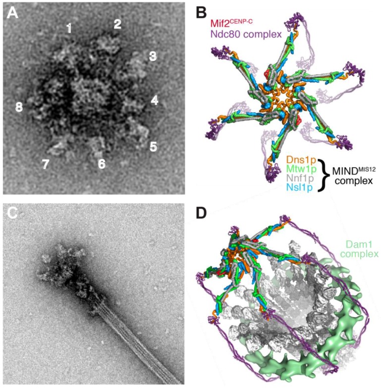
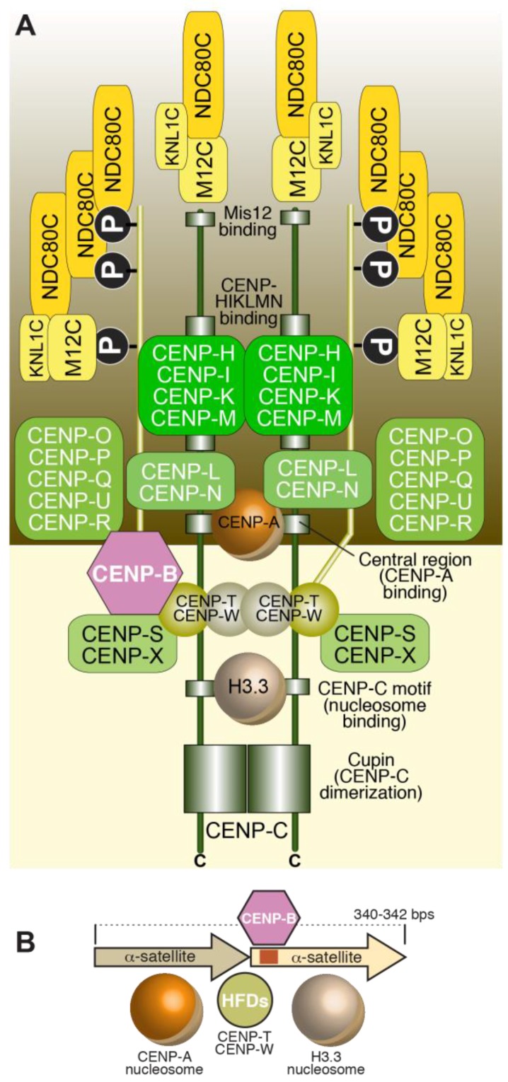
Kinetochores are large protein assemblies that connect chromosomes to microtubules of the mitotic and meiotic spindles in order to distribute the replicated genome from a mother cell to its daughters. Kinetochores also control feedback mechanisms responsible for the correction of incorrect microtubule attachments, and for the coordination of chromosome attachment with cell cycle progression. Finally, kinetochores contribute to their own preservation, across generations, at the specific chromosomal loci devoted to host them, the centromeres. They achieve this in most species by exploiting an epigenetic, DNA-sequence-independent mechanism; notable exceptions are budding yeasts where a specific sequence is associated with centromere function. In the last 15 years, extensive progress in the elucidation of the composition of the kinetochore and the identification of various physical and functional modules within its substructure has led to a much deeper molecular understanding of kinetochore organization and the origins of its functional output. Here, we provide a broad summary of this progress, focusing primarily on kinetochores of humans and budding yeast, while highlighting work from other models, and present important unresolved questions for future studies.

Keywords: CCAN; CENP-A; KMN; cell division; centromere; kinetochore; meiosis; mitosis.


Conflict of interest statement

The authors declare no conflict of interest.

Figures

Figure 1
Figure 1
Kinetochore morphology in vertebrate cells (A) Schematic showing the attachment of chromosomes to spindle microtubules through kinetochores; (B) Early work on the kinetochore identified inner and outer plates, separated by a translucent layer. Microtubules terminate end-on on the kinetochore outer plate. Arrowheads indicate inner plate (IP), outer plate (OP), translucent layer (TL), and kinetochore microtubules (MT). Image reproduced with permission from reference [7]; (C) The corona (Co) is a fibrous structure that is more clearly visible on kinetochores prior to microtubule attachment. Image reproduced with permission from reference [7]; (D,E) Prior to microtubule attachment (D), vertebrate kinetochores adopt a crescent-like shape. The latter is not visible on fully congressed and bi-oriented kinetochores. Images courtesy of Alexey Khodjakov. See also reference [8]; (F) Left: at metaphase, the distributions of two proteins in the inner and outer kinetochores (NDC80 and CENP-A respectively), are similar; Right: After treatment with a microtubule-depolymerizing drug (nocodazole), proteins in the corona (not shown) and in the outer kinetochore undergo an expansion and form the crescent-like shape already shown in D. Image courtesy of Alexey Khodjakov. See also reference [8]; (G) A prometaphase PtK2 cell prepared for electron microscopy by high-pressure freezing and freeze-substitution in glutaraldehyde and Osmium tetroxide. The cell was then embedded in plastic, serial-sectioned with 300 nm sections, and imaged by serial tilting. A 3D reconstruction was computed by back-projection, using the IMOD software package. The slice shown here is about 5 nm thick, and represents the average of two consecutive tomographic planes. Arrowheads indicate slender fibrils connecting the end of microtubules to the kinetochore. Image courtesy of J. Richard McIntosh.
Figure 2
Figure 2
Schematic summary of the structural organization of budding yeast and human kinetochores. Related colors highlight conserved components/complexes. (A) Schematic of the S. cerevisiae kinetochore with subunit names; (B) The S. cerevisiae centromere (CEN) DNA is stereotyped and contains CDEI, CDEII, and CDEIII regions, which bind CBF1, Cse4CENP-A, and CBF3, respectively; (C) Folding of CEN DNA around a Cse4 nucleosome brings CBF1 and CBF3 in close proximity; (D) Schematic of the H. sapiens kinetochore. Orthologous complexes are shown in the same order as in (A); (E) The unit of human centromere assembly may consist of a pair of α-satellite repeats, each precisely wrapping around a nucleosome. One of the two α-satellite repeats carries a CENP-B box. The CENP-TW complex may interact in the inter-nucleosomal region through its histone-fold domain (HFDs) [77,78]. Repeats of this unit give rise to α-satellite arrays, which in turn may organize themselves in higher order repeats (HORs); (F) The human centromere arises from folding of centromeric chromatin in three dimensions to facilitate the participation of several CENP-A nucleosomes in kinetochore assembly.
Figure 3
Figure 3
The CENP-A nucleosome and its specific recognition by CENP-C. (A) Comparison of H3 and CENP-A primary, secondary, tertiary, and quaternary structure. Sequence and structure changes concentrate in the N-terminal region, in the L1 segment of the CATD, and in the C-terminal region; (B) Structure of the complex of the CENP-C motif bound to a nucleosome containing a chimeric histone H3 with grafted hydrophobic C-terminal peptide of CENP-A [79]; (C) Scheme illustrating the organization of CENP-C as a “blueprint” for kinetochore assembly along the outer to inner kinetochore axis [80]. The H3 nucleosome structure is from X. laevis, the CENP-A nucleosome structure is human, and the CENP-C motif-bound structure has a Drosophila nucleosome core particle (in which the human CENP-A tail was grafted onto H3) bound to a rat CENP-C motif.
Figure 4
Figure 4
The NDC80 and MIS12 complexes of the KMN network. (A) The NDC80 complex is highly elongated and interacts with microtubules via calponin-homology (CH) domains in the N-terminal regions of NDC80 and NUF2. A basic N-terminal tail preceding the NDC80 CH domain (depicted as unstructured) is subject to Aurora kinase phosphorylation (Ps in black circles) and regulates microtubule binding. A long coiled-coil, interrupted by a loop (white arrowhead) terminates in a tetramerization domain with SPC24 and SPC25. The latter start with coiled-coils and terminate with RWD domains (red arrowhead), which interact with the MIS12 complex; (B) Rotary shadowing electron microscopy of the NDC80 complex, showing its characteristic dumbbell shape, and an overall length of ~65 nm. Images in (B,D) courtesy of Dr. Pim Huis in ‘t Veld, Max Planck Institute of Molecular Physiology, Dortmund (Germany) [239]; (C) Model from cryo-EM studies of the Ndc80Bonsai complex bound to the microtubule lattice. Only a single α-tubulin:β-tubulin dimer is shown, with two Ndc80Bonsai complexes bound via the toe region; (D) Complexes of the NDC80C and MIS12C are ~85 nm in length; (E) Structural organization of the MIS12 complex bound to the N-terminal region of CENP-C [241]. All structures shown are for the human complexes.
Figure 5
Figure 5
Orchestration of the spindle assembly checkpoint (SAC) by the KMN network SAC components are recruited via the Knl1 subunit that is 2316 residues in humans and is largely disordered. Exceptions are a predicted coiled-coil around residues 1850–2100, and the C-terminal tandem RWD domains, whose crystal structure is shown [235]. The RWD region of Knl1 binds directly to the MIS12 complex [234,235]. The N-terminal half of Knl1 contains multiple MELT repeats (Met-Glu-Leu-Thr) that are targeted by Mps1 kinase (which in turn requires Aurora B kinase to become activated). Each MELT repeat has the potential to assemble active SAC complexes that signal lack of microtubule attachment and arrest the cell cycle in mitosis.
Figure 6
Figure 6
Linkages between the inner and outer kinetochore. Structures of a portion of the NDC80 complex (the N-terminal globular domains of NDC80 and NUF2 are not shown), the MIS12 complex and the C-terminal kinetochore-targeting domain of KNL1 are used to depict a KMN particle in humans. (A) The first linkage is formed by the interaction of a KMN particle with the N-terminal region of CENP-C. This interaction is enhanced by Aurora B phosphorylation of residues (S100 and S109) in the N-terminal region of the DSN1 subunit of the MIS12 complex; (B) The second linkage involves the interaction of up to two NDC80 complexes with two CDK1-phosphorylated residues (T11 & T85) in the N-terminal region of CENP-T, as well as of a second entire KMN recruited via a CDK1-dependent interaction of the MIS12 complex with S201 of CENP-T [239]. In vitro, CENP-C and CENP-T bind to the MIS12 complex within the KMN network competitively, implying that they cannot be bound to the same KMN [239]. All structures shown are for the human complexes.
Figure 7
Figure 7
Images and structural model of budding yeast kinetochore particles. (A) Negative stain electron micrographs showing a kinetochore particle isolated from S. cerevisiae [291]. Images in this panel and in C courtesy of Sue Biggins and Tamir Gonen; (B) A rendered image with possible molecular interpretation of the negatively stained particles showing MINDMIS12:CENP-C complexes departing from a central “hub” and connecting with Ndc80 complexes. Image reproduced with permission from reference [240]; (C) Negative stain electron micrographs showing a S. cerevisiae kinetochore particle bound to the end of a taxol-stabilized microtubule [291]. Image courtesy of Sue Biggins and Tamir Gonen; (D) The structure in (B) is shown to surround the microtubule in end-on configuration. The Dam1 complex stabilizes the arrangement by surrounding the microtubule. Image reproduced with permission from reference [240].
Figure 8
Figure 8
A model for the assembly unit of the human kinetochore. The kinetochore assembly unit is depicted as being organized on a CENP-A-H3.3 dinucleosome. (A) A primary determinant of the stoichiometry of kinetochore subunits is the valency of the CENP-A nucleosome, which confers the potential to interact with two CCAN complexes, as shown in work of in vitro reconstitution of kinetochore assembly [110]. Because CENP-C and CENP-T each carries a full KMN network, and CENP-T additionally carries two NDC80 complexes, there are four MIS12 and KNL1 complexes per CENP-A nucleosome, and up to 8 NDC80 complexes. CENP-C has the potential to interact with two nucleosomes (see Figure 3), with one of them (the one bound to the CENP-C central region) is a CENP-A nucleosome permanently marked by interactions with stably bound CCAN subunits. As clarified in Figure 9, we speculate that the identity of the second nucleosome, which binds to the CENP-C motif, varies during the cell cycle, alternating between CENP-A and H3.3. The C-terminal dimerization domain of CENP-C might “seal” this design. During mitosis, the second nucleosome is an H3.3 nucleosome; (B) This speculative design is compatible with the existence of the tandem α-satellite structures already discussed in Figure 2. CENP-TW is proposed to bind in the inter-nucleosomal linker region, near the CENP-B box.
Figure 9
Figure 9
Cell cycle-regulated replenishment of CENP-A nucleosomes New. CENP-A incorporation takes place after mitotic exit, early in G1 phase (bottom). It is driven by an existing, active CENP-A nucleosome (e.g., because bound to CCAN subunits), and directed on a neighboring nucleosome. Here, we hypothesize that the neighboring nucleosome in humans is already bound to the CENP-C motif of CENP-C. An active MIS18 complex, including M18BP1, recruits HJURP, which binds to pre-nucleosomal CENP-A. The C-terminal region of CENP-C has been implicated in this reaction, which also requires PLK1 activity. A chromatin-remodeling factor and other chromatin-associated factors promote extraction of H3.3 and its replacement with CENP-A through an ATP-dependent reaction. The resulting configuration (top) persists until DNA replication (S-phase), when CENP-A “vacancies” caused by distribution of CENP-A to the sister chromatids during DNA replication, are filled with H3.3. This configuration then persists through the rest of the cell cycle until mitotic exit, because the CENP-A loading machinery is inhibited by CDK activity (middle).

References

    1. Cheeseman I.M. The kinetochore. Cold Spring Harb. Perspect. Biol. 2014;6:a015826. doi: 10.1101/cshperspect.a015826. - DOI - PMC - PubMed
    1. Nagpal H., Fukagawa T. Kinetochore assembly and function through the cell cycle. Chromosoma. 2016;125:645–659. doi: 10.1007/s00412-016-0608-3. - DOI - PubMed
    1. Pesenti M.E., Weir J.R., Musacchio A. Progress in the structural and functional characterization of kinetochores. Curr. Opin. Struct. Biol. 2016;37:152–163. doi: 10.1016/j.sbi.2016.03.003. - DOI - PubMed
    1. McKinley K.L., Cheeseman I.M. The molecular basis for centromere identity and function. Nat. Rev. Mol. Cell Biol. 2016;17:16–29. doi: 10.1038/nrm.2015.5. - DOI - PMC - PubMed
    1. Muller S., Almouzni G. A network of players in H3 histone variant deposition and maintenance at centromeres. Biochim. Biophys. Acta. 2014;1839:241–250. doi: 10.1016/j.bbagrm.2013.11.008. - DOI - PubMed