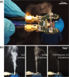
Compact SAW aerosol generator
- PMID: 28127655
- PMCID: PMC5269460
- DOI: 10.1007/s10544-017-0152-9
Compact SAW aerosol generator
Abstract
In this work, we discuss and demonstrate the principle features of surface acoustic wave (SAW) aerosol generation, based on the properties of the fluid supply, the acoustic wave field and the acoustowetting phenomena. Furthermore, we demonstrate a compact SAW-based aerosol generator amenable to mass production fabricated using simple techniques including photolithography, computerized numerical control (CNC) milling and printed circuit board (PCB) manufacturing. Using this device, we present comprehensive experimental results exploring the complexity of the acoustic atomization process and the influence of fluid supply position and geometry, SAW power and fluid flow rate on the device functionality. These factors in turn influence the droplet size distribution, measured here, that is important for applications including liquid chromatography, pulmonary therapies, thin film deposition and olfactory displays.
Keywords: Aerosol source; Atomization; Fluid supply; Mass scale production; Microchannel; Miniaturization; SAW; Surface acoustic wave.
Figures


Similar articles
-
Experimental research on surface acoustic wave microfluidic atomization for drug delivery.Sci Rep. 2022 May 13;12(1):7930. doi: 10.1038/s41598-022-11132-9. Sci Rep. 2022. PMID: 35562384 Free PMC article.
-
Acoustic resonance effects and cavitation in SAW aerosol generation.Ultrason Sonochem. 2023 Aug;98:106530. doi: 10.1016/j.ultsonch.2023.106530. Epub 2023 Jul 24. Ultrason Sonochem. 2023. PMID: 37515911 Free PMC article.
-
SAW-based fluid atomization using mass-producible chip devices.Lab Chip. 2015 Sep 21;15(18):3793-9. doi: 10.1039/c5lc00756a. Lab Chip. 2015. PMID: 26262577
-
SAW-driven droplet jetting technology in microfluidic: A review.Biomicrofluidics. 2020 Dec 9;14(6):061505. doi: 10.1063/5.0014768. eCollection 2020 Nov. Biomicrofluidics. 2020. PMID: 33343781 Free PMC article. Review.
-
A Comprehensive Review of Surface Acoustic Wave-Enabled Acoustic Droplet Ejection Technology and Its Applications.Micromachines (Basel). 2023 Jul 31;14(8):1543. doi: 10.3390/mi14081543. Micromachines (Basel). 2023. PMID: 37630082 Free PMC article. Review.
Cited by
-
Experimental research on surface acoustic wave microfluidic atomization for drug delivery.Sci Rep. 2022 May 13;12(1):7930. doi: 10.1038/s41598-022-11132-9. Sci Rep. 2022. PMID: 35562384 Free PMC article.
-
Atomic-Scale Modeling of Water and Ice Behavior on Vibrating Surfaces: Toward the Design of Surface Acoustic Wave Anti-icing and Deicing Systems.Langmuir. 2025 May 13;41(18):11293-11306. doi: 10.1021/acs.langmuir.4c04330. Epub 2025 May 1. Langmuir. 2025. PMID: 40311150 Free PMC article.
-
Surface acoustic wave devices for chemical sensing and microfluidics: A review and perspective.Anal Methods. 2017;9(28):4112-4134. doi: 10.1039/C7AY00690J. Epub 2017 Jun 13. Anal Methods. 2017. PMID: 29151901 Free PMC article.
-
Fully Microfabricated Surface Acoustic Wave Tweezer for Collection of Submicron Particles and Human Blood Cells.ACS Appl Mater Interfaces. 2023 May 24;15(20):24023-24033. doi: 10.1021/acsami.3c00537. Epub 2023 May 15. ACS Appl Mater Interfaces. 2023. PMID: 37188328 Free PMC article.
-
Acoustic resonance effects and cavitation in SAW aerosol generation.Ultrason Sonochem. 2023 Aug;98:106530. doi: 10.1016/j.ultsonch.2023.106530. Epub 2023 Jul 24. Ultrason Sonochem. 2023. PMID: 37515911 Free PMC article.
References
-
- Alghane M, Chen B, Fu Y, Li Y, Luo J, Walton A. Journal of micromechanics and Microengineering. 2011;21(1):015005. doi: 10.1088/0960-1317/21/1/015005. - DOI
-
- Altshuler G, Manor O. Physics of fluids. 2015;27(10):18. doi: 10.1063/1.4932086. - DOI
-
- M. Alvarez, J.R. Friend, L.Y. Yeo, Nanotechnology 19, (2008) - PubMed
-
- Y. Ariyakul, T. Nakamoto, in TENCON 2014–2014 I.E. Region 10 Conference (2014), pp. 1–5
Publication types
MeSH terms
Substances
LinkOut - more resources
Full Text Sources
Other Literature Sources

