. 2016 Nov 23;2(11):e1601019.
doi: 10.1126/sciadv.1601019. eCollection 2016 Nov.

Reconfigurable origami-inspired acoustic waveguides

Affiliations

Reconfigurable origami-inspired acoustic waveguides

Sahab Babaee et al. Sci Adv. .

Abstract

We combine numerical simulations and experiments to design a new class of reconfigurable waveguides based on three-dimensional origami-inspired metamaterials. Our strategy builds on the fact that the rigid plates and hinges forming these structures define networks of tubes that can be easily reconfigured. As such, they provide an ideal platform to actively control and redirect the propagation of sound. We design reconfigurable systems that, depending on the externally applied deformation, can act as networks of waveguides oriented along one, two, or three preferential directions. Moreover, we demonstrate that the capability of the structure to guide and radiate acoustic energy along predefined directions can be easily switched on and off, as the networks of tubes are reversibly formed and disrupted. The proposed designs expand the ability of existing acoustic metamaterials and exploit complex waveguiding to enhance control over propagation and radiation of acoustic energy, opening avenues for the design of a new class of tunable acoustic functional systems.

Keywords: Acoustic waveguide; metamaterial; origami; reconfigurable; sound.


Figures

Fig. 1
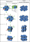
Fig. 1. Reconfigurable origami-inspired acoustic waveguides.
Experimental and actual models of the building block (the extruded cube) and the corresponding reconfigurable acoustic metamaterial deformed into three different configurations: (a) (α1, α2, α3) = (π/2, π/2, π/2), (b) (α1, α2, α3) = (π/2, π/2, 0), and (c) (α1, α2, α3) = (π/3, 2π/3, π/3). The red arrows and shaded areas indicate the excited waves, whereas the green arrows and shaded areas highlight the points from which the structure radiates.
Fig. 2
Fig. 2. Experimental setup.
Experimental setup without the sound-absorbing foam surrounding the sample.
Fig. 3
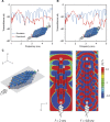
Fig. 3. Propagation of sound waves for (α1, α2, α3) = (π/2, π/2, 0).
(A) Model of the metamaterial. (B) Top cross-sectional view of the pressure field distribution at f = 3.5 kHz. The cutting plane is shown in (A), and the color indicates the pressure amplitude normalized by the input signal amplitude (P0). (C) Frequency-dependent transmittance for the sample where experimental (red lines), numerical (blue line), and analytical (dashed black lines) results are shown.
Fig. 4
Fig. 4. Propagation of sound waves for (α1, α2, α3) = (π/3, 2π/3, π/3).
(A and B) Frequency-dependent transmittances of the sample calculated considering two different detection points. Both experimental (red lines) and numerical (blue lines) results are shown. (C) Model of the metamaterial and top cross-sectional view of the pressure field distribution at f = 2 and 4.8 kHz. The cutting plane is shown in gray (left), and the color map indicates the pressure amplitude normalized by the input signal amplitude P0 (right).
Fig. 5
Fig. 5. Propagation of sound waves for (α1, α2, α3) = (π/2, π/2, π/2).
(A and B) Frequency-dependent transmittances of the sample calculated considering two different detection points. Both experimental (red lines) and numerical (blue lines) results are shown. (C) Model of the metamaterial and cross-sectional view of the pressure field distribution at f = 2 and 4.8 kHz. The cutting plane is shown in gray (left), and the color map indicates the pressure amplitude normalized by the input signal amplitude P0 (right).
Fig. 6
Fig. 6. Reconfigurable acoustic waveguide based on a tessellation of truncated octahedra.
Models of the building block and the corresponding reconfigurable acoustic metamaterial deformed into three different configurations: (a) θ = π/4, (b) θ = 0, and (c) θ = π/2.
Fig. 7
Fig. 7. Reconfigurable acoustic waveguide based on a tessellation of hexagonal prisms.
Models of the building block and the corresponding reconfigurable acoustic metamaterial deformed into four different configurations: (a) (α,γ) = (0,0), (b) (α,γ) = (π/4, − π/4), (c) (α,γ) = (−π/4, − π/4), and (d) (α,γ) = (π/4, π/4).

References

    1. Selamet A., Dickey N. S., Novak J. M., The Herschel–Quincke tube: A theoretical, computational, and experimental investigation. J. Acoust. Soc. Am. 96, 3177–3185 (1994).
    1. Poirier B., Maury C., Ville J.-M., The use of Herschel–Quincke tubes to improve the efficiency of lined ducts. Appl. Acoust. 72, 78–88 (2011).
    1. Depollier C., Kergomard J., Lesueur J. C., Propagation of low frequency acoustic waves in periodic 2D-lattices of tubes. J. Sound Vib. 142, 153–170 (1990).
    1. Molerón M., Félix S., Pagneux V., Richoux O., Sound propagation in periodic urban areas. J. Appl. Phys. 111, 114906 (2012).
    1. Lang R. J., Origami: Complexity increasing. Eng. Sci. 52, 16–23 (1989).