Review
. 2017 Jan;60(1):12-24.
doi: 10.3164/jcbn.16-64. Epub 2016 Dec 17.

Destruction of biological particles using non-thermal plasma

Affiliations
Review

Destruction of biological particles using non-thermal plasma

Akira Mizuno. J Clin Biochem Nutr. 2017 Jan.

Abstract

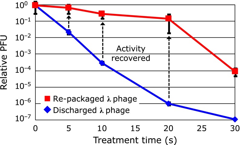
Mechanism of inactivation of bio-particles exposed to non-thermal plasma (NTP), namely, dielectric barrier discharge (DBD), and plasma jet (PJ), has been studied using E. coli, B. subtilis spore, S. cerevisiae and bacteriophages. States of different biological components were monitored during the course of inactivation. Analysis of green fluorescent protein, GFP, introduced into E. coli. or B. subtiles spore cells proved that radicals generated by NTP penetrate into microbes, destroying the cell membrane and finally damage the genes. We have evaluated the damage of the bacteriophages. Bacteriophage λ having double stranded DNA was exposed to DBD, then DNA was purified and subjected to in vitro DNA packaging reactions. The re-packaged phages consist of the DNA from discharged phages and brand-new coat proteins were proved to be active, indicating that the damage of coat proteins is responsible for inactivation. M13 phages having single stranded DNA were also examined with the same manner. In this case, damage to the DNA was as severe as that of the coat proteins. For practical applications, DBD showed very intense sterilization ability for B. Subtilis spore with the D-value of less than 10 s. This result indicates a possibility of application of NTP for quick sterilization.

Keywords: dielectric barrier discharge; non-thermal plasma; plasma jet; radical; sterilization.


Conflict of interest statement

No potential conflicts of interest were disclosed.

Figures

Fig. 1
Fig. 1
Collection of suspended bio-particles in air using electrostatic precipitation. (a) An electrostatic precipitator for collecting bio-particles in air. (b) Number of colony due to collected bio-particles using the ESP.
Fig. 2
Fig. 2
Radial distribution of the colonies collected by the electrostatic precipitation (electrode separation: 10 mm). (a) Positive corona. (b) Negative corona.
Fig. 3
Fig. 3
Electrical discharging devices used in the experiment. (a) Dielectric barrier discharge. (b) Plasma jet.
Fig. 4
Fig. 4
Bacillus subtilis spores differentially labeled with GFP.
Fig. 5
Fig. 5
Sterilization using dielectric barrier discharge. (a) Dry sample. (b) Wet sample.
Fig. 6
Fig. 6
Plasma bleaching of fused-GFP in the spores.
Fig. 7
Fig. 7
Survival rate and the GFP fluorescence of the E. coli after the DBD treatment (Power density: 0.4 W/cm2).
Fig. 8
Fig. 8
Fluorescent image of the E. coli producing GFP. 0–20 s fluorescent of GFP, 30–80 s fluorescent of DNA by adding YOYO-1. Bar: 20 µm.
Fig. 9
Fig. 9
SDS polyacrylamide gel electrophoresis of E. coli MV1184 (pGLO) exposed to the DBD. Cells were lysed and fractionated in a 14% gel before staining with Coomassie Brilliant Blue (CBB). Lane M is a protein standards marker, lane 1 is purified GFP, lane 2 is non-induced E. coli MV1184 (pGLO), lanes 3–8 represent the cells treated with DBD for 0, 5, 10, 20, 30 and 40 s, respectively. The arrow indicates GFP.
Fig. 10
Fig. 10
Agarose gel electrophoresis of the cellular DNA from E. coli MV1184 (pGLO) exposed to the DBD. (a) DNA was extracted and separated in 0.3% gel before staining with ethidium bromide. Lane M1 is Hind III digests of λDNA, lane M2 is monomeric λDNA. Lanes 1–6 represent the DNA from the cells treated with DBD for 0, 5, 10, 20, 30 and 40 s, respectively. Arrows indicate chromosome DNA. (b) Plasmid DNA fractionated in 0.8% gel. Lane M represents the purified pGLO DNA. Lanes 1–6 represent the plasmid DNA fraction from the cells treated with DBD for 0, 5, 10, 20, 30 and 40 s, respectively. sc, oc and l represent super-coiled, open circler, and linear form, respectively. (c) Plasmid DNA fractionated in 0.8% gel from the purified DNA subjected to DBD. Lane M represents the purified pGLO DNA. Lanes 1–6 represent the naked DNA samples treated with DBD for 0, 5, 10, 20, 30 and 40 s, respectively.
Fig. 11
Fig. 11
Decrease in fluorescent intensity and survival rate of the GFP-expressing E. coli by the exposure to plasma jet.
Fig. 12
Fig. 12
Cell density and E. coli survival rate with cultivation time from early exponential phase, through transition phase (6 h) to stationary phase, after the plasma jet exposure.
Fig. 13
Fig. 13
The yeast reporter assay system.
Fig. 14
Fig. 14
Response of the yeast reporter assay ((a)–(f) fold induction) and the survival rate of the yeast vs exposure time of the plasma jet (g). The plasma jet was used with the voltage of 16 kVp-p, 3.5 kHz with Ar or He of 2 L/min gas flow rate. The sample was set in a 96-well container. Distance between the nozzle of the PJ and the surface of the sample was 25 mm. (a) MMS (methyl methanesulfonate), (b) H2O2, (c) UV lamp, (d) Heat shock (40°C), (e) Ar plasma jet, (f) He plasma jet, (g) Survival rate.
Fig. 15
Fig. 15
Inactivation of φX174 phage by the exposure to DBD. (a, b) Wet sample. (c, d) Dry sample. PFU: plaque forming unit. (a) Wet φX174 phage and φX174 DNA. (b) Wet φX174 phage coat protein (SDS-PAGE). (c) Dry φX174 phage and φX174 DNA. (d) Dry φX174 phage coat protein (SDS-PAGE).
Fig. 16
Fig. 16
Electrophoresis of the protein and the extracted DNA from λ phage treated by the DBD. (a) SDS gel electrophoresis λ phage. Lane M: protein marker, lane 0: large amount of purified λ phage, lanes 1–6 represent the proteins from the phages treated with the DBD for 0, 5, 10, 20, 30 and 40 s. (b) Electrophoresis of the extracted DNA. Lane M1: monomeric DNA, lane M2: Hind III digests of λ DNA, lanes 1–6: DNA from the phages treated with the DBD for 0, 5, 10, 20, 30 and 40 s.
Fig. 17
Fig. 17
Method to identify the damage of bacteriophage by NTP exposure.
Fig. 18
Fig. 18
Relative PFU (plaque forming unit) curves obtained from the re-packaged λ phages and the discharged (plasma treated) phages.

References

    1. Mizuno A. Industrial applications of atmospheric non-thermal plasma in environmental remediation. Plasma Physics and Controlled Fusion. 2007;49:A1–A15.
    1. Mizuno A, Yamazaki Y, Ito H, Yoshida H. Ac energized ferroelectric pellet bed gas cleaner. IEEE Trans Ind Appl. 1992;28:535–540.
    1. Yasuda H, Hashimoto M, Rahman M, Takashima K, Mizuno A. States of biological components in bacteria and bacteriophages during inactivation by atmospheric dielectric barrier discharges. Plasma Process Polym. 2008;5:615–621.
    1. Fridman G, Brooks AD, Balasubramanian M, et al. Comparison of direct and indirect effects of non-thermal atmospheric-pressure plasma on bacteria. Plasma Process Polym. 2007;4:370–375.
    1. Hashimoto M, Rahman MM, Tanino M, et al. Cell destruction by dielectric barrier discharge for real-time monitoring of bio-particles. Int J Plasma Environ Sci Technol. 2007;1:146–150.