. 2017 Feb 6;7(1):20160085.
doi: 10.1098/rsfs.2016.0085.

Wind and water tunnel testing of a morphing aquatic micro air vehicle

Affiliations

Wind and water tunnel testing of a morphing aquatic micro air vehicle

Robert Siddall et al. Interface Focus. .

Abstract

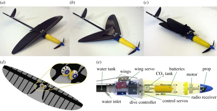
Aerial robots capable of locomotion in both air and water would enable novel mission profiles in complex environments, such as water sampling after floods or underwater structural inspections. The design of such a vehicle is challenging because it implies significant propulsive and structural design trade-offs for operation in both fluids. In this paper, we present a unique Aquatic Micro Air Vehicle (AquaMAV), which uses a reconfigurable wing to dive into the water from flight, inspired by the plunge diving strategy of water diving birds in the family Sulidae. The vehicle's performance is investigated in wind and water tunnel experiments, from which we develop a planar trajectory model. This model is used to predict the dive behaviour of the AquaMAV, and investigate the efficacy of passive dives initiated by wing folding as a means of water entry. The paper also includes first field tests of the AquaMAV prototype where the folding wings are used to initiate a plunge dive.

Keywords: aerial–aquatic locomotion; multimodal mobility; wing morphing.


Figures

Figure 1.
Figure 1.
Plunge diving in nature. (a) Northern gannet (Morus bassanus, 3 kg mass) in flight, and (b) with folded wings about to dive into the water. (c) Common kingfisher (Alcedo atthis, 0.03 kg mass) in a dive with wings partially folded and (d) with wings fully folded. Images reproduced under a creative commons licence, courtesy of: Andreas Trepte (a), Mike Pennington (b), Ryan Cheng (c) and Andy Morffew (d). (Online version in colour.)
Figure 2.
Figure 2.
Jet propelled launch by a previous AquaMAV prototype. (a) The AquaMAV uses a pressurized water jet to escape the water. (b) Timelapse of an AquaMAV launch, with wings opened in the final frame. Images adapted from [11]. (Online version in colour.)
Figure 3.
Figure 3.
The AquaMAV airframe. (ac) Fabricated prototype, shown with wings open (a) and swept 45° (b) and 90° (c) backward. (d) CAD rendering of the wings, showing the lay-up pattern and gear linkage. (e) CAD illustration of fuselage, with internal components labelled. (Online version in colour.)
Figure 4.
Figure 4.
CAD drawings of wind tunnel test apparatus. (a) Close-up of worm drive system for angle of attack adjustments, with force balance attached. (b) AquaMAV model location in wind tunnel, showing worm drive and force balance attached to the tunnel floor. (c) AquaMAV model location in water tunnel (shown with wings folded). Panels (b,c) are on the same scale. (Online version in colour.)
Figure 5.
Figure 5.
Lift and drag of the AquaMAV airframe in air, as measured in a wind tunnel, with the RMS error of the force measurements indictated by the shaded region. Increased error can be seen as the wing nears stall due to the unsteady flow. (a) Lift force in Newtons, (b) drag force in Newtons and (c) lift to drag ratio. (Online version in colour.)
Figure 6.
Figure 6.
Centre of pressure of the wing and its variation with angle of attack. (a) Centre of pressure definition from measured forces and moments at the sensor. (b) Measured centre of pressure of the open and closed wing, defined here by the distance from the AquaMAV nose, with the AquaMAV shown on the same scale for illustration.
Figure 7.
Figure 7.
Lift and drag of fuselage and fins. (a) Fuselage only, measured with wings and tail removed. (b) Tail fins only, with fuselage lift and drag subtracted from measurements. (c) Open wing only. (d) Fully retracted wing only. Note that (a,b) are plotted on a different scale to (c,d).
Figure 8.
Figure 8.
The effect of partially sweeping the wings on wing aerodynamics. (a) The range of lift coefficients produced at angles of attack between −2° and 20° in 2° increments, plotted for different wing sweep angles. (b) Lift to drag ratio. (c) Wing sweep sequence with the centre segment removed, showing the interference between segments as they fold. Image at 0° sweep is repeated, with the first image showing the centre segment.
Figure 9.
Figure 9.
The effect of the folding design on the open wing's aerodynamic efficiency. (a) Lift curves for the main wing at 6, 8 and 10 m s−1 compared with a rigid aluminium wing at the same speeds. (b) Drag coefficients for the rigid and folding wing. The fuselage drag, measured separately is subtracted from the folding wing measurements, but the rigid wing still exhibits lower drag, suggesting that the flow around the fuselage interferes with the wing detrimentally. (c) Image of the AquaMAV main wing in the wind tunnel and (d) image of the rigid aluminium wing in the wind tunnel.
Figure 10.
Figure 10.
Fuselage drag measurements at 0° angle of attack in a water tunnel, with a quadratic curve fitted to extract CD.
Figure 11.
Figure 11.
Nomenclature for the equations of motion used in the planar trajectory model, showing the earth-fixed reference frame formula image the robot-fixed reference frame, with its origin at the vehicle nose formula image and illustrating the definition of body angle of attack, αcg, pitch angle θ and velocity angle with respect to the earth-fixed frame, βcg. Also pictured are the wing and tail aerodynamic forces (Lw, Dw and Lf, Df, respectively), the robot weight formula image and buoyancy B.
Figure 12.
Figure 12.
The steady state behaviour of the AquaMAV in an unpowered dive simulated in 3 d.f. using tunnel data, showing the effect of the residual lift of the main wing after folding. (a) Velocity profile of the diving AquaMAV. (b) Velocity profile of the vehicle if wing lift coefficient is artificially set to zero, but wing drag is retained. (c) Pitch and angle attack during a dive. (d) Pitch and angle of attack with zero wing lift. (e) Dive trajectories in both cases. The plots show that while the wing lift has little effect on the impact velocity, which is largely determined by drag, it has a strong effect on the impact angle.
Figure 13.
Figure 13.
The effect on speed and height when wings are folded on the water impact conditions. Each marker represents one trajectory simulation. (a) Impact velocity against dive start height at 8–18 m s−1 start speed. (b) Angle from horizontal at impact. (c) Horizontal distance covered between wing fold and impact.
Figure 14.
Figure 14.
Trajectory of the AquaMAV underwater under changing initial angle and speed. (a) Example dive trajectories for impact at 20 m s−1; the AquaMAV does not initially pitch over, but as its speed reduces and the aerodynamic surfaces no longer generate significant force, the rearward centre of buoyancy rotates it nose down. (b) Dive depth against impact velocity, plotted for various initial angles. An image of the AquaMAV is included on the same scale as the Y-axis.
Figure 15.
Figure 15.
Validity of the quasi-steady assumption for the trajectories shown in §6, evaluated in terms of reduced frequency, k. (a) k against time for trajectories in figure 12, showing that k is below 0.04 for the majority of the simulation. (b) k against absolute velocity for trajectories plotted in figure 14b, showing that the quasi-steady assumption is reasonable for most of the trajectory, until the vehicle's motion is almost arrested, at which point the pitch rate becomes significant relative to the forward velocity.
Figure 16.
Figure 16.
Preliminary flight test of the AquaMAV outdoors. (a) Composite image of a dive into water, with frames 83 ms apart. The impact velocity was estimated from the later video frames. (b) Calibration frame using vehicle length as reference. (c) Final frame showing tracked points. (d) Velocity estimate from tracked points. (e) Image of the AquaMAV at the point of impact with the water. (f) Image of the AquaMAV fully immersed after a dive.

Similar articles

Cited by

References

    1. Ropert-Coudert Y, Grémillet D, Ryan P, Kato A, Naito Y, Le Maho Y. 2004. Between air and water: the plunge dive of the Cape gannet Morus capensis. Ibis 146, 281–290. (10.1111/j.1474-919x.2003.00250.x) - DOI
    1. Siddall R, Kovac M. 2014. Launching the AquaMAV: bioinspired design for aerial–aquatic robotic platforms. Bioinspir. Biomim. 9, 031001 (10.1088/1748-3182/9/3/031001) - DOI - PubMed
    1. Shkurti F, et al. 2012. Multi-domain monitoring of marine environments using a heterogeneous robot team. In 2012 IEEE/RSJ Int. Conf. on Intelligent Robots and Systems (IROS), pp. 1747–1753. New York, NY: IEEE.
    1. Murphy RR, Steimle E, Lindemuth M, Trejo D, Hall M, Slocum D, Hurlebaus S, Medina-Cetina Z et al. . 2009. Robot-assisted bridge inspection after Hurricane Ike. In 2009 IEEE Int. Workshop on Safety, Security and Rescue Robotics (SSRR), pp. 1–5. New York, NY: IEEE.
    1. Lock R, Burgess S, Vaidyanathan R. 2014. Multi-modal locomotion: from animal to application. Bioinspir. Biomim. 9, 011001 (10.1088/1748-3182/9/1/011001) - DOI - PubMed