

Tissue-engineered 3D microvessel and capillary network models for the study of vascular phenomena
- PMID: 28164421
- PMCID: PMC6726128
- DOI: 10.1111/micc.12360
Tissue-engineered 3D microvessel and capillary network models for the study of vascular phenomena
Abstract
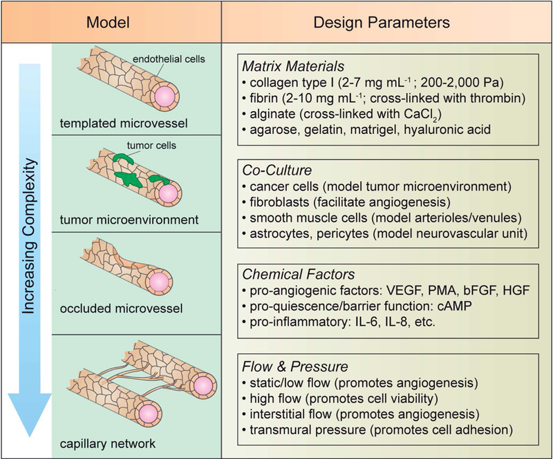
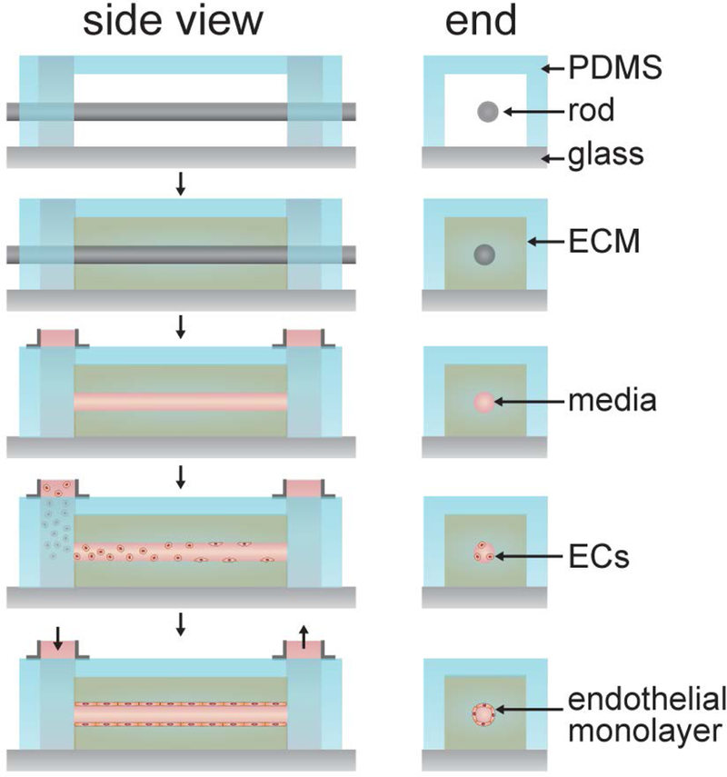
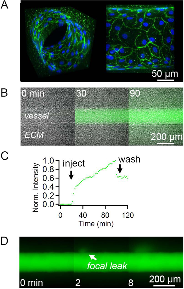
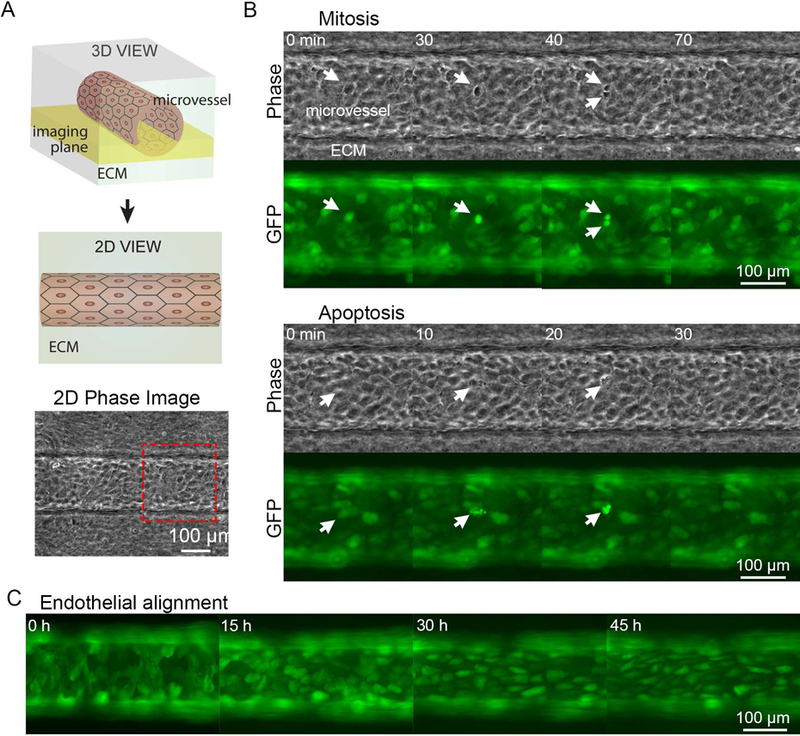
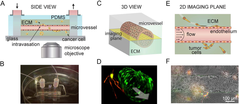
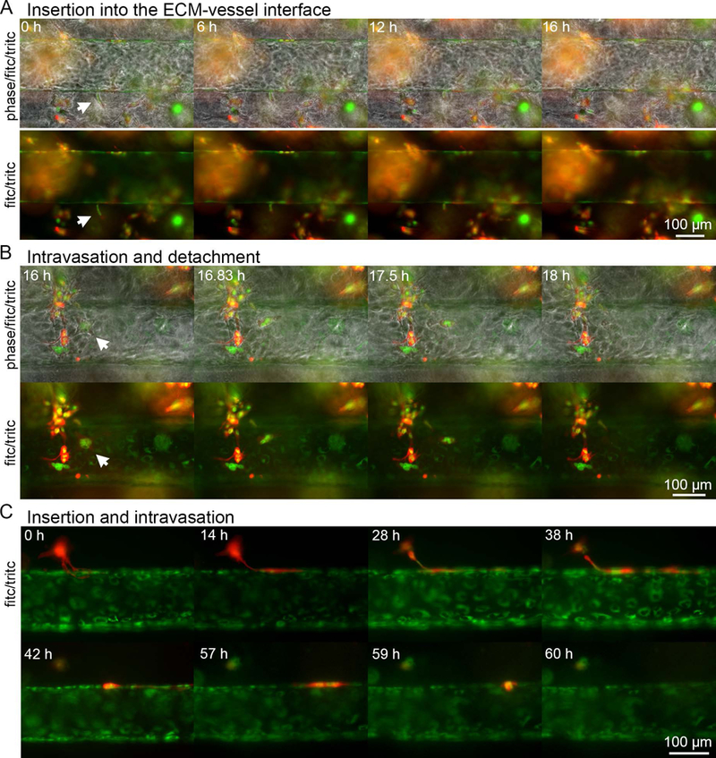
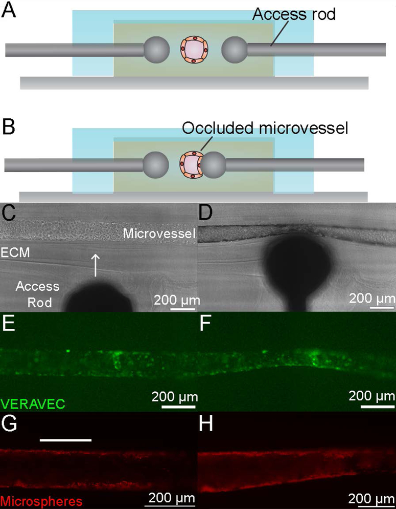
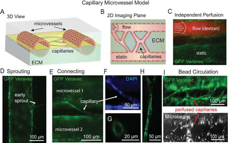
Advances in tissue engineering, cell biology, microfabrication, and microfluidics have led to the development of a wide range of vascular models. Here, we review platforms based on templated microvessel fabrication to generate increasingly complex vascular models of (i) the tumor microenvironment, (ii) occluded microvessels, and (iii) perfused capillary networks. We outline fabrication guidelines and demonstrate a number of experimental methods for probing vascular function such as permeability measurements, tumor cell intravasation, flow characterization, and endothelial cell morphology and proliferation.
Keywords: capillary networks; metastasis; microfabrication; microfluidics; microvascular models; self-organization; templating; vessel occlusion.
© 2017 John Wiley & Sons Ltd.
Conflict of interest statement
Conflict of Interest
None
Figures
Similar articles
-
Leveraging avidin-biotin interaction to quantify permeability property of microvessels-on-a-chip networks.Am J Physiol Heart Circ Physiol. 2022 Jan 1;322(1):H71-H86. doi: 10.1152/ajpheart.00478.2021. Epub 2021 Nov 12. Am J Physiol Heart Circ Physiol. 2022. PMID: 34767485 Free PMC article.
-
Cellular Based Strategies for Microvascular Engineering.Stem Cell Rev Rep. 2019 Apr;15(2):218-240. doi: 10.1007/s12015-019-09877-4. Stem Cell Rev Rep. 2019. PMID: 30739276 Review.
-
A Tissue-Engineered 3D Microvessel Model Reveals the Dynamics of Mosaic Vessel Formation in Breast Cancer.Cancer Res. 2020 Oct 1;80(19):4288-4301. doi: 10.1158/0008-5472.CAN-19-1564. Epub 2020 Jul 14. Cancer Res. 2020. PMID: 32665356 Free PMC article.
-
Mitosis-Mediated Intravasation in a Tissue-Engineered Tumor-Microvessel Platform.Cancer Res. 2017 Nov 15;77(22):6453-6461. doi: 10.1158/0008-5472.CAN-16-3279. Epub 2017 Sep 18. Cancer Res. 2017. PMID: 28923855 Free PMC article.
-
Cell-microenvironment interactions and architectures in microvascular systems.Biotechnol Adv. 2016 Nov 1;34(6):1113-1130. doi: 10.1016/j.biotechadv.2016.07.002. Epub 2016 Jul 11. Biotechnol Adv. 2016. PMID: 27417066 Free PMC article. Review.
Cited by
-
Realizations of vascularized tissues: From in vitro platforms to in vivo grafts.Biophys Rev (Melville). 2023 Mar;4(1):011308. doi: 10.1063/5.0131972. Epub 2023 Mar 13. Biophys Rev (Melville). 2023. PMID: 36938117 Free PMC article. Review.
-
Cell Chirality as a Novel Measure for Cytotoxicity.Adv Biol (Weinh). 2022 Jan;6(1):e2101088. doi: 10.1002/adbi.202101088. Epub 2021 Nov 19. Adv Biol (Weinh). 2022. PMID: 34796704 Free PMC article. Review.
-
Effect of shear stress on iPSC-derived human brain microvascular endothelial cells (dhBMECs).Fluids Barriers CNS. 2017 Aug 4;14(1):20. doi: 10.1186/s12987-017-0068-z. Fluids Barriers CNS. 2017. PMID: 28774343 Free PMC article.
-
Vascularized Biomaterials to Study Cancer Metastasis.Adv Healthc Mater. 2020 Apr;9(8):e1901459. doi: 10.1002/adhm.201901459. Epub 2020 Jan 24. Adv Healthc Mater. 2020. PMID: 31977160 Free PMC article. Review.
-
Engineering the human blood-brain barrier at the capillary scale using a double-templating technique.Adv Funct Mater. 2022 Jul 25;32(30):2110289. doi: 10.1002/adfm.202110289. Epub 2022 May 6. Adv Funct Mater. 2022. PMID: 36312050 Free PMC article.
References
-
- Aird W. Spatial and temporal dynamics of the endothelium. Journal of Thrombosis and Haemostasis 3: 1392–1406, 2005. - PubMed
-
- Aird WC. Phenotypic heterogeneity of the endothelium II. Representative vascular beds. Circulation research 100: 174–190, 2007. - PubMed
-
- Bachmeier CJ, Trickler WJ, Miller DW. Comparison of drug efflux transport kinetics in various blood-brain barrier models. Drug metabolism and disposition: the biological fate of chemicals 34: 998–1003, 2006. - PubMed
-
- Blackman BR, Garcia-Cardena G, Gimbrone MA Jr. A new in vitro model to evaluate differential responses of endothelial cells to simulated arterial shear stress waveforms. J Biomech Eng 124: 397–407, 2002. - PubMed
Publication types
MeSH terms
Grants and funding
LinkOut - more resources
Full Text Sources
Other Literature Sources
