Quasistatic Cavity Resonance for Ubiquitous Wireless Power Transfer
- PMID: 28199321
- PMCID: PMC5310757
- DOI: 10.1371/journal.pone.0169045
Quasistatic Cavity Resonance for Ubiquitous Wireless Power Transfer
Abstract
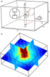
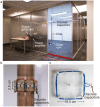
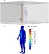
Wireless power delivery has the potential to seamlessly power our electrical devices as easily as data is transmitted through the air. However, existing solutions are limited to near contact distances and do not provide the geometric freedom to enable automatic and un-aided charging. We introduce quasistatic cavity resonance (QSCR), which can enable purpose-built structures, such as cabinets, rooms, and warehouses, to generate quasistatic magnetic fields that safely deliver kilowatts of power to mobile receivers contained nearly anywhere within. A theoretical model of a quasistatic cavity resonator is derived, and field distributions along with power transfer efficiency are validated against measured results. An experimental demonstration shows that a 54 m3 QSCR room can deliver power to small coil receivers in nearly any position with 40% to 95% efficiency. Finally, a detailed safety analysis shows that up to 1900 watts can be transmitted to a coil receiver enabling safe and ubiquitous wireless power.
Conflict of interest statement
Figures


References
-
- Deyle T, Reynolds M. Surface based wireless power transmission and bidirectional communication for autonomous robot swarms. IEEE International Conference on Robotics and Automation, 2008 ICRA 2008. 2008. pp. 1036–1041.
-
- Scheible G, Schutz J, Apneseth C. Novel wireless power supply system for wireless communication devices in industrial automation systems. IECON 02 [Industrial Electronics Society, IEEE 2002 28th Annual Conference of the]. 2002. pp. 1358–1363 vol.2.
-
- Waters BH, Sample AP, Bonde P, Smith JR. Powering a Ventricular Assist Device (VAD) With the Free-Range Resonant Electrical Energy Delivery (FREE-D) System. Proc IEEE. 2012;100: 138–149. 10.1109/JPROC.2011.2165309 - DOI
-
- Li P, Bashirullah R. A Wireless Power Interface for Rechargeable Battery Operated Medical Implants. IEEE Trans Circuits Syst II Express Briefs. 2007;54: 912–916. 10.1109/TCSII.2007.901613 - DOI
-
- Hoang H, Lee S, Kim Y, Choi Y, Bien F. An adaptive technique to improve wireless power transfer for consumer electronics. IEEE Trans Consum Electron. 2012;58: 327–332. 10.1109/TCE.2012.6227430 - DOI
MeSH terms
LinkOut - more resources
Full Text Sources
Other Literature Sources

