. 2017:3:16.
doi: 10.1051/sicotj/2016043. Epub 2017 Feb 21.

Putting 3D modelling and 3D printing into practice: virtual surgery and preoperative planning to reconstruct complex post-traumatic skeletal deformities and defects

Affiliations

Putting 3D modelling and 3D printing into practice: virtual surgery and preoperative planning to reconstruct complex post-traumatic skeletal deformities and defects

Kevin Tetsworth et al. SICOT J. 2017.

Abstract

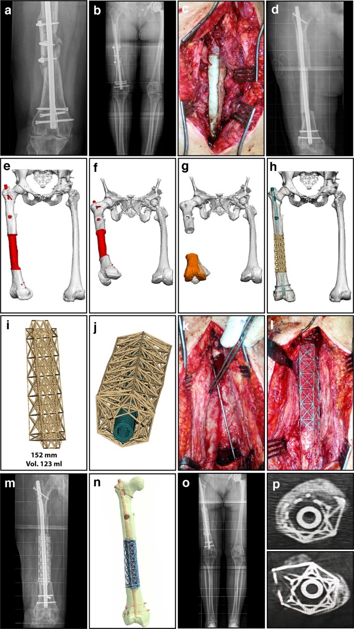
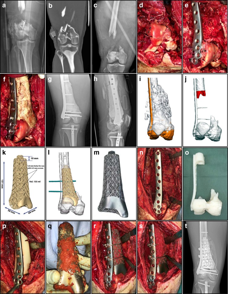
3D printing technology has revolutionized and gradually transformed manufacturing across a broad spectrum of industries, including healthcare. Nowhere is this more apparent than in orthopaedics with many surgeons already incorporating aspects of 3D modelling and virtual procedures into their routine clinical practice. As a more extreme application, patient-specific 3D printed titanium truss cages represent a novel approach for managing the challenge of segmental bone defects. This review illustrates the potential indications of this innovative technique using 3D printed titanium truss cages in conjunction with the Masquelet technique. These implants are custom designed during a virtual surgical planning session with the combined input of an orthopaedic surgeon, an orthopaedic engineering professional and a biomedical design engineer. The ability to 3D model an identical replica of the original intact bone in a virtual procedure is of vital importance when attempting to precisely reconstruct normal anatomy during the actual procedure. Additionally, other important factors must be considered during the planning procedure, such as the three-dimensional configuration of the implant. Meticulous design is necessary to allow for successful implantation through the planned surgical exposure, while being aware of the constraints imposed by local anatomy and prior implants. This review will attempt to synthesize the current state of the art as well as discuss our personal experience using this promising technique. It will address implant design considerations including the mechanical, anatomical and functional aspects unique to each case.


Figures

Figure 1.
Figure 1.
Diaphyseal femoral segmental defect (15.2 cm) – infected non-union. (a) Anteroposterior (AP) radiograph of femoral mid-diaphyseal infected non-union, with a sequestrum consisting of the remnants of a prior intercalary allograft. (b) Long-standing radiograph of femoral mid-diaphyseal infected non-union, demonstrating alignment and limb lengths. (c) Intra-operative image during the 1st stage, illustrating a temporary antibiotic-loaded PMMA spacer. (d) Radiograph showing an antibiotic-loaded PMMA spacer fashioned to completely fill the defect, enveloping the bone at both the proximal and distal ends. (e) 3D modelling image showing the antibiotic spacer spanning the defect. (f) Axial view of 3D modelling image, demonstrating a 32° internal rotation deformity. (g) 3D virtual procedure images showing the distal fragment internal rotation of 32°, malaligned in 5° excess valgus, and flexed 9°, with a 12 mm residual limb length discrepancy. The planning for correcting the orientation of the distal fragment (amber), restoring its normal anatomic position by using the mirrored image of the contralateral uninvolved normal limb as a template. (h) 3D virtual procedure images showing the truss cage implant, designed to allow stabilization by a large diameter nail. (i) Final titanium truss implant design for the mid-diaphyseal femur, with tapered intramedullary extensions to improve torsional and translational stability. (j) The truss implant design here incorporates an axial hole designed to fit a suitable IM nail for stabilization of the mid-diaphyseal femur. (k) Intra-operative image during the second stage after the PMMA spacer was removed, demonstrating the membrane. (l) Intra-operative image during the second stage, following insertion of the titanium implant with bone graft packed into the open cells of the truss cage. (m) AP radiograph illustrating the final position of the implant, with a nail inserted through the truss cage locked proximally and distally. (n) Computer rendered image of the definitive reconstruction, stabilized with a nail inserted through the truss cage. (o) Long-standing radiograph of the lower extremities post-operatively, demonstrating excellent alignment and equal limb lengths. (p) CT scan at six-month post-operative confirming solid incorporation of bone graft, best demonstrated at the host/implant junctions proximally and distally.
Figure 2.
Figure 2.
Metadiaphyseal distal femoral segmental defect (15.1 cm) – Grade 3A open fracture. (a) AP radiograph of this Grade 3A open R distal femur fracture immediately following the injury. (b) Initial CT scan demonstrating loss of bone stock and cartilage centrally, with less than 6 mm of bone adjacent to the intercondylar notch. (c) AP radiograph of the distal femur after initial debridement and spanning external fixation. (d) Intra-operative photos during the 1st stage, with reconstruction of the highly comminuted intra-articular extension of the fracture. (e) Intra-operative image showing the fracture reduced anatomically and then stabilized with a locked plate. (f) Intra-operative image during the 1st stage showing the PMMA spacer temporarily filling the defect, augmenting mechanical support of the distal segment while also providing a surface for the development of an induced membrane. (g) AP radiograph following stabilization with a lateral locked plate, incorporating an antibiotic-loaded PMMA spacer. (h) Lateral radiograph of the distal femur with plate and temporary PMMA spacer. (i) The patient-specific 3D printed titanium truss implant was produced after first conducting a virtual surgical procedure. (j) Additional bone was resected (red) to facilitate the actual procedure and to maximize contact and inherent stability. (k) Dimensions of the 3D printed titanium truss implant, designed with a tapered intramedullary extension proximally that increases stability significantly. (l) The truss implant design included trajectories for screw holes that correspond to the existing implant (green). (m) The final implant was produced with a polished surface to articulate with the patella, indicating extent of cartilage loss. The design of the implant very closely mimics the contours and dimensions of the original bone. (n) Intra-operative image during the second stage, with carefully opened and preserved membrane after the PMMA spacer was removed. (o) 3D printed acrylic model of the anticipated final skeletal defect, used to confirm satisfactory fit and alignment of the implant. (p) Intra-operative image showing insertion of a plastic template to assess the adequacy of the final resection, used as a trial before inserting the implant. (q) Before implantation, the truss construct was filled with autologous and allogeneic cancellous bone graft mixed with powdered vancomycin, then manually packed into the open cells of the truss implant. (r) Intra-operative image showing the truss implant filled with bone graft and inserted into the defect, with additional fixation including two cerclage cables. (s) Intra-operative image during the second stage, showing additional bone graft packed over the anterior and medial aspects of the truss implant after definitive fixation was completed. (t) AP radiograph demonstrating early incorporation of the bone graft, with a solid column of dense bridging bone visible medially four months after the procedure.

References

    1. Grant CA, Izatt MT, Labrom RD, Askin GN, Glatt V (2016) Use of 3D printing in complex spinal surgery: historical perspectives, current usage, and future directions. Tech Orthop 31(3), 172–180.
    1. Green N, Glatt V, Tetsworth K, Wilson LJ, Grant CA (2016) A practical guide to image processing in the creation of 3d models for orthopedics. Tech Orthop 31(3), 153–163.
    1. Kalamaras M, McEniery P, Thorn K, Bindra R (2016) Rapid prototyping and 3D modeling of osteotomy jigs and drill guides in hand and wrist surgery. Tech Orthop 31(3), 164–171.
    1. Smith KE, Dupont KM, Safranski DL, Blair JW, Buratti DR, Zeetser V, Callahan R, Lin JS, Gall K (2016) Use of 3D printed bone plate in novel technique to surgically correct hallux valgus deformities. Tech Orthop 31(3), 181–189. - PMC - PubMed
    1. Tetsworth K (2016) Three-dimensional modeling, rapid prototypes, and additive manufacturing: the diffusion of innovation and the adoption of technology in orthopedic surgery. Tech Orthop 31(3), 141–142.

LinkOut - more resources