. 2017 Feb 23;8(1):7.
doi: 10.1038/s41467-016-0008-7.

CLK-dependent exon recognition and conjoined gene formation revealed with a novel small molecule inhibitor

Affiliations

CLK-dependent exon recognition and conjoined gene formation revealed with a novel small molecule inhibitor

Tyler Funnell et al. Nat Commun. .

Abstract

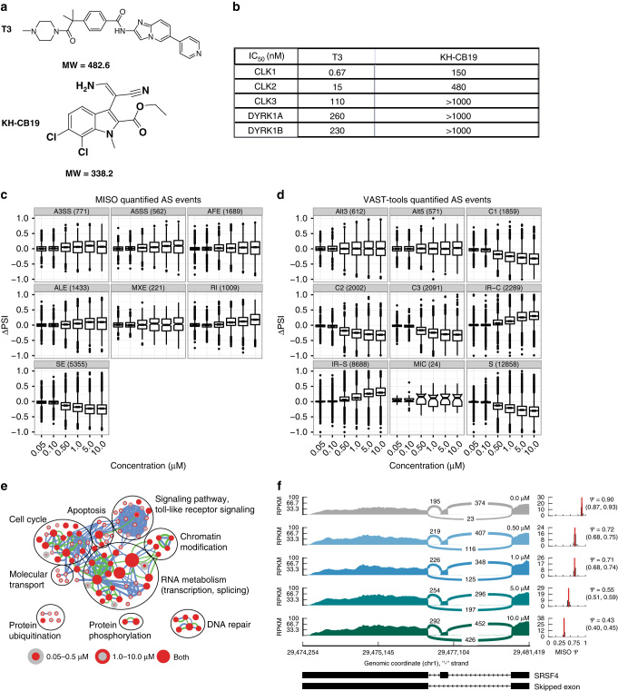
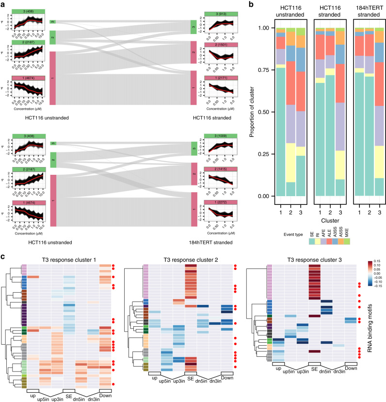
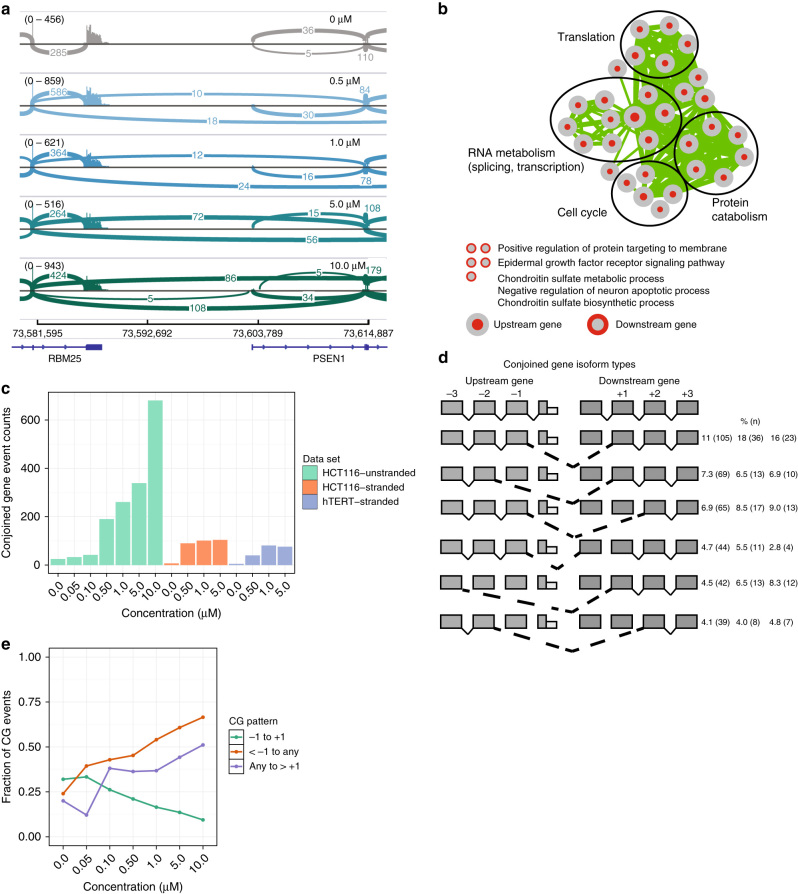
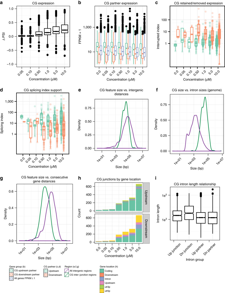
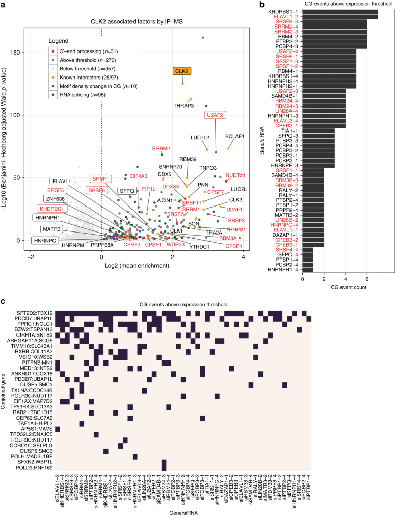
CDC-like kinase phosphorylation of serine/arginine-rich proteins is central to RNA splicing reactions. Yet, the genomic network of CDC-like kinase-dependent RNA processing events remains poorly defined. Here, we explore the connectivity of genomic CDC-like kinase splicing functions by applying graduated, short-exposure, pharmacological CDC-like kinase inhibition using a novel small molecule (T3) with very high potency, selectivity, and cell-based stability. Using RNA-Seq, we define CDC-like kinase-responsive alternative splicing events, the large majority of which monotonically increase or decrease with increasing CDC-like kinase inhibition. We show that distinct RNA-binding motifs are associated with T3 response in skipped exons. Unexpectedly, we observe dose-dependent conjoined gene transcription, which is associated with motif enrichment in the last and second exons of upstream and downstream partners, respectively. siRNA knockdown of CLK2-associated genes significantly increases conjoined gene formation. Collectively, our results reveal an unexpected role for CDC-like kinase in conjoined gene formation, via regulation of 3'-end processing and associated splicing factors.The phosphorylation of serine/arginine-rich proteins by CDC-like kinase is a central regulatory mechanism for RNA splicing reactions. Here, the authors synthesize a novel small molecule CLK inhibitor and map CLK-responsive alternative splicing events and discover an effect on conjoined gene transcription.


Figures

Fig. 1
Fig. 1
AS responses to T3 analyzed by event type and biological enrichment. a Chemical structure of “T3” and KH-CB19. b Inhibition spectrum of the compounds for CLK1, CLK2, CLK3, DYRK1A, and DYRK1B (1 mM of ATP was used for CLK1, CLK2, CLK3, DYRK1A, and DYRK1B kinase). c MISO AS event type ∆PSI distributions across CLK inhibitor concentration for the HCT116 unstranded RNA-Seq data set. Horizontal axis categories are concentrations of T3. SE, RI, A5SS, and A3SS event classes are as described in the main text; AFE: alternative first exon, ALE: alternative last exon, MXE: mutually exclusive exon. Event counts in parentheses. d VAST-tools AS event type ∆PSI distributions across CLK inhibitor concentration for the HCT116 unstranded RNA-Seq data set. Horizontal axis categories are concentrations of T3. VAST-tools event types are: S, C1, C2, C3: SE with increasing complexity, MIC: skipped microexons, IR-S: RI not overlapping another annotated event, IR-C: RI overlapping another annotated event, Alt3: alternative acceptor site, Alt5: alternative donor site. Event counts in parentheses. e BP enrichment map for differentially spliced genes in the HCT116 unstranded RNA-Seq data set. Each node represents a GO BP gene set. Node cores are colored red when that gene set is enriched among genes differentially spliced in the 0.05–0.5 µM samples, and the outer ring is colored red when that gene set is enriched in the 1.0–10.0 µM samples. Nodes present in both are solid colored. Edge thickness indicates the level of overlap between two gene sets, considering the set of differentially spliced genes in the 0.05–0.5 µM (green edges) or 1.0–10.0 µM (blue edges) samples. f Sashimi style plot of exon skipping events associated with the SRSF4 gene. RPKM values are displayed as 0–100 along the vertical axis and genome coordinates (bp) along the horizontal axis. Each strip represents increasing T3 concentration, value displayed on the right. The number of events represented by each splice event are inserted in the center of the curved lines. Right of the main plot, MISO PSI posterior distribution
Fig. 2
Fig. 2
CLKi responsive AS gene clusters analyzed by event type. a PSI cluster profiles and relationships between HCT116 and 184hTERT cell types. The schematic is organized as a sankey diagram in the center, showing the relationships between AS events within clusters (vertical bars, with cluster number), pairwise in each of the three data sets. Events associated with increasing PSI have a green colored bar/title, those with decreasing PSI a red colored bar. The gray lines show the relationship between common members. The PSI vs. T3 dose response plots are shown aligned to the cluster they represent. Black lines represent AS event PSI profiles. The vertical axis represents standardized PSI score. The horizontal axis represents T3 concentration (µM). Red lines are cluster eigen-events. The number of events in each cluster is shown in parentheses in the cluster label, which is colored green for clusters that increase in PSI with increasing T3 concentration and red for clusters that decrease with T3. b Cluster event type proportions. The proportion of MISO event types in each cluster is shown as a stacked bar plot. The event key is shown below. c Heatmap showing RBP motifs with a significant density difference in PSI cluster 1 (monotonic PSI decrease cluster), 2 and 3 (PSI increase clusters) SE sequences compared to other PSI clusters for HCT116 unstranded RNA-Seq ∆SE events. Only one motif per RBP family is shown, for full display with labels see Supplementary Figs. 21, 22, 23. Horizontal axis represents seven SE event sequence regions analyzed: up (upstream exon), up5in and up3in (5′ and 3′ sections of the upstream intron), SE, dn5in and dn3in (5′ and 3′ sections of the downstream intron), and dn (downstream exon). Cells with non-significant differences are colored gray. Colored cells represent a positive (red) or negative (blue) effect size. Color bars on the left of vertical axis represent a possible motif cluster assignment based on significance and effect size patterns. Red dots indicate splicing factors associated with CLK family proteins
Fig. 3
Fig. 3
Characteristics of CG transcripts induced by inhibition of CLK. a IGV-generated sashimi plot of the RBM25-PSEN1 CG. Plots for T3 treatment concentrations of 0.0, 0.5, 1.0, 5.0, and 10.0 µM are shown from top to bottom. The control sample plot is colored gray, and the treated sample plots are colored according to T3 concentration. RefSeq gene annotations are shown in blue at the bottom of the plot along with chromosome 12 coordinates (bp). For each sample, the y-axis represents read coverage normalized by (1,000,000/total reads), and the value range is indicated between brackets. Arcs connecting exons represent reads spliced across introns, with the number of spliced reads annotated over the line. Only arcs representing at least five reads are shown. b Enrichment map for genes involved in CGs in the HCT116 unstranded RNA-Seq data set. Each node represents a GO BP gene set. BP enriched in CG upstream partners have red cores, while BP enriched in downstream partners have red outer rings. Edge thickness indicates the level of CG partner overlap between gene sets. c CG counts per RNA-Seq library as detected by a modified deFuse classifier. d Top CG splicing patterns for the HCT116 unstranded RNA-Seq data set. Schematic shows the most abundant conjoined splicing relationships between in-cis gene pairs. Right of figure, percentage of all CG events (number of events in class) for HCT116 unstranded, HCT116 stranded, and 184hTERT stranded libraries, respectively. e Dose-dependent CG splicing pattern proportions across T3 concentrations for the HCT116 unstranded RNA-Seq data set. As T3 concentration is increased, more exons are skipped. See panel d for splicing patterns
Fig. 4
Fig. 4
Expression and genomic features of CGs for HCT116 unstranded libraries. See Supplementary Figs. 30, 33 for HCT116 stranded and 184hTERT data set plots. a CG ∆PSI boxplots, per T3 treatment concentration. b Boxplots of FPKM values for CG upstream and downstream participants, compared to all genes with FPKM ≥ 1 (i.e., expressed genes). c Boxplots of interrupted indices for CGs across T3 concentrations. Interrupted indices are calculated as the ratio of coverage between the portions of a gene retained and removed by CGs (Supplementary Fig. 32a). Boxplots are shown for the upstream and downstream CG participants. d Boxplots of splicing indices for CGs across T3 concentrations. Splicing indices are calculated as the number of concordant read pairs spanning a CG splice junction in a CG participant, divided by the number of CG splice junction spanning reads that support the presence of a CG (Supplementary Fig. 32b). Boxplots are shown for the upstream and downstream CG participants. e Density plot of CG splice junction distances vs. gene distances in the genome. f Density plot of CG splice junction distances vs. intron lengths of multi-exonic protein coding genes in the genome. g Density plot of CG participant distances vs. consecutive gene distances in the genome. h Barplots showing the number of CG splice junctions falling within different annotated gene locations, across T3 concentrations. Barplots for the upstream and downstream CG participants are shown. i Boxplots of intron lengths for introns adjacent to the upstream and downstream CG splice junction, and all introns in upstream and downstream CG gene partners
Fig. 5
Fig. 5
Heatmap showing significant RBP motif density differences in CG sequences. Heatmap is for all HCT116 and 184hTERT CGs compared to non-CG sequences. X-axis represents four CG sequence regions: penultimate (−1 exon) exon, last exon (0, terminal exon of upstream participant), first exon downstream (0, first exon of downstream participant), second exon (+1, downstream partner). Only one motif per RBP family is shown, the number of motifs in square brackets. Y-axis shows the RBP motif id and RBP name (highlighted red: CLK interactors) and protein domains associated with the listed motif. Cells with non-significant differences are colored gray. Colored cells represent a positive (red) or negative (blue) effect size. Color bars on the left y-axis represent a possible motif cluster assignment based on significance and effect size patterns
Fig. 6
Fig. 6
Proteins associated with CLK2 and implicated in CG expression. a Volcano plot ranking proteins associated with CLK2 IP identified by four pull downs of N-terminal FLAG tagged, one untagged CLK2 and one control empty vector, determined by TMT mass spectrometry. The log2 mean fold enrichment (horizontal axis) and enrichment p-value were determined by linear model fits to MS determined peptide abundance. Known CLK2 interactors,,, orange dots; known spliceosome-associated proteins (PantherGO), green dots; factors associated with RNA-binding motifs enriched in CG exons are boxed and their dots blue; factors associated with 3′-end processing highlighted in red. Threshold is adjusted to <0.05 and log2(mean enrichment) >0. b Number of CG events above expression threshold after siRNA knockdown. siRNA to splicing factors (vertical axis, highlighted red: 3′-end processing factors) assessed by a quantitative, targeted NGS sequencing panel for specific CG events was used to quantify CG expression in relation to non-targeting controls. The plot displays the number of CG events per knockdown condition, expressed more than 2 SD above the mean of ≥3 non-targeting controls or the number of CG events per knockdown condition where CG expression in the non-targeting controls was undetectable (see also Supplementary Fig. 36). c Heatmap showing distribution of individual CG event occurrence (vertical axis) above the control expression threshold (as in panel b). The presence of a black square indicates one or more CG events

Similar articles

Cited by

References

    1. Kornblihtt AR, et al. Alternative splicing: a pivotal step between eukaryotic transcription and translation. Nat. Rev. Mol. Cell Biol. 2013;14:153–165. doi: 10.1038/nrm3525. - DOI - PubMed
    1. Modrek B, Lee CJ. Alternative splicing in the human, mouse and rat genomes is associated with an increased frequency of exon creation and/or loss. Nat. Genet. 2003;34:177–180. doi: 10.1038/ng1159. - DOI - PubMed
    1. Wang ET, et al. Alternative isoform regulation in human tissue transcriptomes. Nature. 2008;456:470–476. doi: 10.1038/nature07509. - DOI - PMC - PubMed
    1. Fu X-D, Ares M. Context-dependent control of alternative splicing by RNA-binding proteins. Nat. Rev. Genet. 2014;15:689–701. doi: 10.1038/nrg3778. - DOI - PMC - PubMed
    1. Krawczak M, Reiss J, Cooper DN. The mutational spectrum of single base-pair substitutions in mRNA splice junctions of human genes: causes and consequences. Hum. Genet. 1992;90:41–54. doi: 10.1007/BF00210743. - DOI - PubMed

Publication types

MeSH terms