

An Analytical Method to Calculate Phantom Scatter Factor for Photon Beam Accelerators
- PMID: 28243402
- PMCID: PMC5308490
- DOI: 10.19082/3523
An Analytical Method to Calculate Phantom Scatter Factor for Photon Beam Accelerators
Abstract
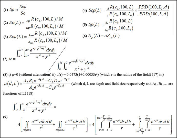
Introduction: One of the important input factors in the commissioning of the radiotherapy treatment planning systems is the phantom scatter factor (Sp) which requires the same collimator opening for all radiation fields. In this study, we have proposed an analytical method to overcome this issue.
Methods: The measurements were performed using Siemens Primus Plus with photon energy 6 MV for field sizes from 5×5cm2 to 40×40cm2. Phantom scatter factor was measured through the division of total scatter output factors (Scp), and collimator scatter factor (Sc).
Results: The mean percent difference between the measured and calculated Sp was 1.00% and -3.11% for 5×5, 40×40 cm2 field size respectively.
Conclusion: This method is applicable especially for small fields used in IMRT which, measuring collimator scatter factor is not reliable due to the lateral electron disequilibrium.
Keywords: Phantom scatter factor; Radiotherapy; Total scatter factor.
Conflict of interest statement
Conflict of Interest: There is no conflict of interest to be declared.
Figures


Similar articles
-
Determination of the Small-Field Output Factor for 6 MV Photon Beam Using EGSnrc Monte Carlo.J Med Phys. 2022 Jul-Sep;47(3):301-308. doi: 10.4103/jmp.jmp_40_22. Epub 2022 Nov 8. J Med Phys. 2022. PMID: 36684700 Free PMC article.
-
The determination of phantom and collimator scatter components of the output of megavoltage photon beams: measurement of the collimator scatter part with a beam-coaxial narrow cylindrical phantom.Radiother Oncol. 1991 Apr;20(4):250-7. doi: 10.1016/0167-8140(91)90124-y. Radiother Oncol. 1991. PMID: 1906190 Review.
-
An analytical formalism to calculate phantom scatter factors for flattening filter free (FFF) mode photon beams.Phys Med Biol. 2014 Feb 21;59(4):951-60. doi: 10.1088/0031-9155/59/4/951. Epub 2014 Feb 7. Phys Med Biol. 2014. PMID: 24503449
-
Head scatter factors for small MV photon fields. Part I: a comparison of phantom types and methodologies.Radiother Oncol. 2007 Nov;85(2):277-85. doi: 10.1016/j.radonc.2007.09.005. Epub 2007 Nov 5. Radiother Oncol. 2007. PMID: 17983677
-
A Monte Carlo study on internal wedges using BEAM.Med Phys. 2002 May;29(5):876-85. doi: 10.1118/1.1473132. Med Phys. 2002. PMID: 12033584
Cited by
-
Interpretation of In-air Output Ratio of Wedged Fields in Different Measurement Conditions.J Med Signals Sens. 2019 Apr-Jun;9(2):117-122. doi: 10.4103/jmss.JMSS_36_18. J Med Signals Sens. 2019. PMID: 31316905 Free PMC article.
-
Determination of the Small-Field Output Factor for 6 MV Photon Beam Using EGSnrc Monte Carlo.J Med Phys. 2022 Jul-Sep;47(3):301-308. doi: 10.4103/jmp.jmp_40_22. Epub 2022 Nov 8. J Med Phys. 2022. PMID: 36684700 Free PMC article.
References
-
- Khan FM, Gibbons JP. Khan’s the physics of radiation therapy. Lippincott Williams & Wilkins; 2014.
-
- Khan FM. med Phy. 4 ed. 2012. The physics of radiation therapy; pp. 148–52.
-
- Iftikhar A. Measurements of output factors using different ionization chambers and build up caps. Iranian Journal of Radiation Research. 2012;10(2):95–8.
LinkOut - more resources
Full Text Sources
Other Literature Sources