. 2017 Feb 17:11:10.
doi: 10.3389/fninf.2017.00010. eCollection 2017.

Automatic and Precise Localization and Cortical Labeling of Subdural and Depth Intracranial Electrodes

Affiliations

Automatic and Precise Localization and Cortical Labeling of Subdural and Depth Intracranial Electrodes

Chaoyi Qin et al. Front Neuroinform. .

Abstract

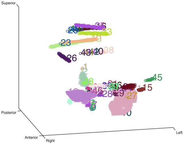
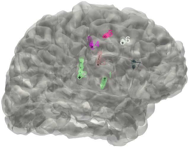
Object: Subdural or deep intracerebral electrodes are essential in order to precisely localize epileptic zone in patients with medically intractable epilepsy. Precise localization of the implanted electrodes is critical to clinical diagnosing and treatment as well as for scientific studies. In this study, we sought to automatically and precisely extract intracranial electrodes using pre-operative MRI and post-operative CT images. Method: The subdural and depth intracranial electrodes were readily detected using clustering-based segmentation. Depth electrodes were tracked by fitting a quadratic curve to account for potential bending during the neurosurgery. The identified electrodes can be manipulated using a graphic interface and labeled to cortical areas in individual native space based on anatomical parcellation and displayed in the volume and surface space. Results: The electrodes' localizations were validated with high precision. The electrode coordinates were normalized to a standard space. Moreover, the probabilistic value being to a specific area or a functional network was provided. Conclusions: We developed an integrative toolbox to reconstruct and label the intracranial electrodes implanted in the patients with medically intractable epilepsy. This toolbox provided a convenient way to allow inter-subject comparisons and relation of intracranial EEG findings to the larger body of neuroimaging literature.

Keywords: ECoG; SEEG; electrode localization; intracranial EEG; intractable epilepsy.


Figures

Figure 1
Figure 1
Clustering-based automatic segmentation for electrode detection. Color-coded clusters with unique number are displayed in a stereo space. The real electrode-related clusters can be detected by specifying the corresponding cluster number. Rotating and zooming functions can be used to facilitate this process.
Figure 2
Figure 2
The distribution of electrodes. The clusters detected for the implanted electrodes are superimposed on the individual brain surface. The electrodes shown can be rearranged in a right order if needed.
Figure 3
Figure 3
Validation of the electrode reconstruction. The points marked by A, B, C, D, E, F, and G are the outer positions of the depth electrodes included in the validation step for 4 patients. The left panel denotes the real electrodes' positions from an intraoperative picture and the right panel denotes the reconstructed electrodes' positions on the pial.
Figure 4
Figure 4
Density map. Volume and surface view of a density map (here for instance brain activity map shown in power spectrum). The warm-color voxels indicate the positive value and cool-color for the negative value. The volume image was displayed in a radiology view (i.e., left side = right hemisphere).
Figure 5
Figure 5
Peri-coronal view for displaying an electrode strip. (A) Showing typically orthogonal SEEG electrodes in coronal view. (B) Showing a full SEEG electrode displaying in a non-orthogonal coronal view.
Figure 6
Figure 6
Subdural electrode reconstruction, manual correction, and surface projection. (A) The subdural grid contacts are detected by the automatic process. The missing and dislocated contacts can be easily recognized. (B) The final electrode arrays are displayed on the pial surface after manual correction. (C) Due to the brain deformation caused by electrode implantation, some electrode points appear to be buried beneath the cortical surface. (D) The electrode arrays are projected onto the brain surface.
Figure 7
Figure 7
Display electrodes of one patient. Showing all the electrodes' relative positions on a rendered cortical surface using color and number to differentiate.
Figure 8
Figure 8
Electrodes representation in standard space. The electrodes' distributions of patients included in the validation process on a standard MNI152 surface, green dots indicate contacts in white matter area; blue dots indicate contacts in gray matter area.

Similar articles

Cited by

References

    1. Arnulfo G., Narizzano M., Cardinale F., Fato M. M., Palva J. M. (2015). Automatic segmentation of deep intracerebral electrodes in computed tomography scans. BMC Bioinformatics 16:99. 10.1186/s12859-015-0511-6 - DOI - PMC - PubMed
    1. Desikan R. S., Segonne F., Fischl B., Quinn B. T., Dickerson B. C., Blacker D., et al. . (2006). An automated labeling system for subdividing the human cerebral cortex on MRI scans into gyral based regions of interest. Neuroimage 31, 968–980. 10.1016/j.neuroimage.2006.01.021 - DOI - PubMed
    1. Dykstra A. R., Chan A. M., Quinn B. T., Zepeda R., Keller C. J., Cormier J., et al. . (2012). Individualized localization and cortical surface-based registration of intracranial electrodes. Neuroimage 59, 3563–3570. 10.1016/j.neuroimage.2011.11.046 - DOI - PMC - PubMed
    1. Engel A. K., Moll C. K., Fried I., Ojemann G. A. (2005). Invasive recordings from the human brain: clinical insights and beyond. Nat. Rev. Neurosci. 6, 35–47. 10.1038/nrn1585 - DOI - PubMed
    1. Fischl B., Salat D. H., Busa E., Albert M., Dieterich M., Haselgrove C., et al. . (2002). Whole brain segmentation: automated labeling of neuroanatomical structures in the human brain. Neuron 33, 341–355. 10.1016/S0896-6273(02)00569-X - DOI - PubMed