. 2017 Jan 9;8(2):712-725.
doi: 10.1364/BOE.8.000712. eCollection 2017 Feb 1.

Optics of the human cornea influence the accuracy of stereo eye-tracking methods: a simulation study

Affiliations

Optics of the human cornea influence the accuracy of stereo eye-tracking methods: a simulation study

A D Barsingerhorn et al. Biomed Opt Express. .

Abstract

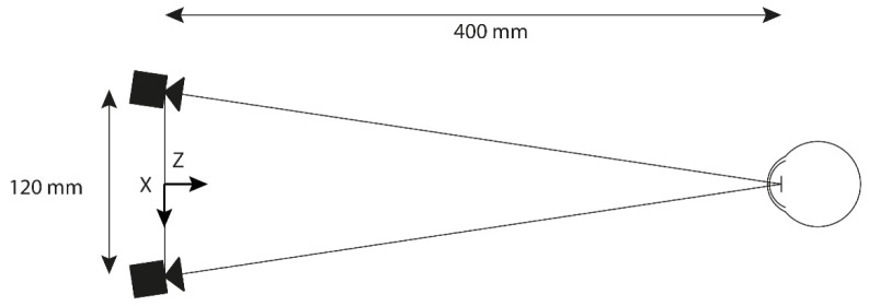
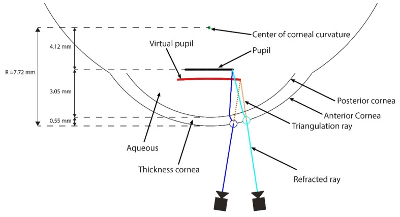
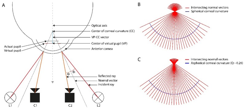
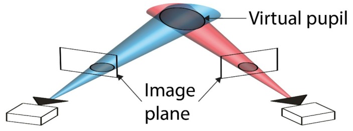
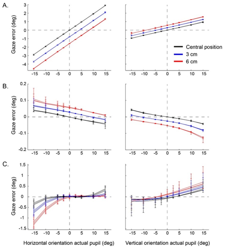
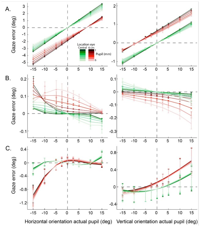
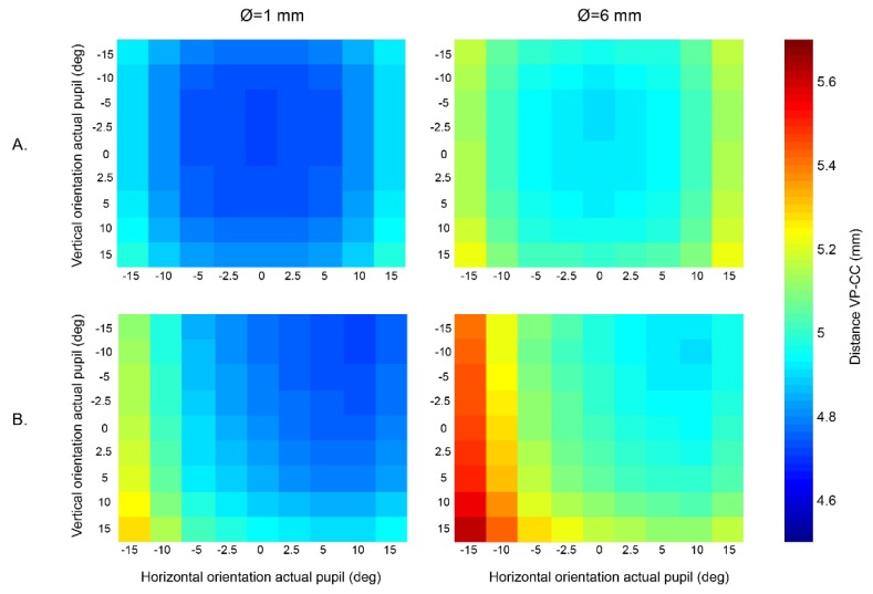
Current stereo eye-tracking methods model the cornea as a sphere with one refractive surface. However, the human cornea is slightly aspheric and has two refractive surfaces. Here we used ray-tracing and the Navarro eye-model to study how these optical properties affect the accuracy of different stereo eye-tracking methods. We found that pupil size, gaze direction and head position all influence the reconstruction of gaze. Resulting errors range between ± 1.0 degrees at best. This shows that stereo eye-tracking may be an option if reliable calibration is not possible, but the applied eye-model should account for the actual optics of the cornea.

Keywords: (330.2210) Vision - eye movements; (330.4460) Ophthalmic optics and devices; (330.7326) Visual optics, modeling.


Figures

Fig. 1
Fig. 1
Top view of the simulated stereo eye-tracking set-up. Two virtual cameras were placed 120 mm apart, with their nodal points 60 mm left and right from the origin in a right-handed coordinate system. The optical axis of both cameras intersect at 400 mm from the origin in the horizontal plane. The simulated eye was placed at different spatial locations (X∈[0, 30, 60] mm, Y∈[0, 30, 60] mm and Z = 400 mm).
Fig. 2
Fig. 2
3D reconstruction of the virtual pupil. For each point on the pupil boundary the refracted ray that passes through the nodal point of the camera was determined. Subsequently, the refracted rays from both cameras were triangulated to obtain the 3D coordinates of each corresponding point of the virtual pupil. Parameters of the Navarro eye model are indicated on the left-hand side.
Fig. 3
Fig. 3
Estimation of the center of corneal curvature. A. The ray-trace model to estimate the center of corneal curvature based on a spherical anterior cornea, L1 and L2 are the light sources, C1 and C2 are the cameras. The incident ray is reflected at the anterior corneal surface. The angle of incidence θi is equal to the angle of reflection θr. The normal vectors intersect at the center of corneal curvature. B. The intersecting normal vectors in case of a spherical corneal curvature. C. The normal vectors at the surface of an aspherical cornea.
Fig. 4
Fig. 4
Gaze reconstruction using conic algebra. For each camera a cone can be projected through the projection of the virtual pupil at the image plane. The virtual pupil lies at the intersection of these cones.
Fig. 5
Fig. 5
Location, orientation and shape of the virtual pupil obtained through ray tracing compared to the actual pupil for two different cases. A. The actual pupil is rotated 15 degrees to the right. Top view of the simulation. B. The actual pupil is rotated 15 degrees up. Side view of the simulation. The optical axis (OA) always goes through the fixed center of corneal curvature (fCC) and the center of the actual pupil (AP). The 3D shape of the virtual pupil boundary varied between conditions. A plane was fit through the boundary points of the virtual pupil (VPplane). The normal vector of this plane (VPnorm) was used to describe the orientation of the virtual pupil. The VP-CC vector is defined by the estimated center of corneal curvature (CC) and the center of the virtual pupil (VP).
Fig. 6
Fig. 6
Reconstruction of gaze direction with stereo eye-tracking methods compared to the orientation of the actual and virtual pupil. A. The actual pupil was positioned at the central location between both cameras (X = 0mm, Y = 0mm, Z = 400mm). B. The actual pupil was shifted 6 cm to the left and 6 cm downwards, simulating a translation of the head.
Fig. 7
Fig. 7
Accuracy of the different gaze reconstruction methods for a fixed pupil diameter of 4 mm. A. the conic algebra method. B. the VP-fCC method. C. the VP-CC method. Each plot shows the horizontal/vertical gaze reconstruction errors as a function of the horizontal/vertical orientation of the actual pupil for each of the nine different pupil/head translations. Data are averaged either across the nine different vertical pupil orientations (left-hand plots) or the nine different horizontal pupil orientations (right-hand plots). Colors identify the magnitude of the horizontal (left-hand plots) or vertical (right-hand plots) translation. Note the scaling differences between plots A, B and C.
Fig. 8
Fig. 8
The effect of pupil size on stereo eye-tracking methods. A. the conic algebra method. B. the VP-fCC method. C. the VP-CC method. The mean and range of the gaze errors is plotted for all pupil diameters at two head positions. The dashed lines indicate the results for a pupil diameter of 4 mm. For clarity of the graph, the actual pupil was only translated horizontally (left-hand plots) or vertically (right-hand plots). Note the scaling differences between the horizontal and vertical errors.
Fig. 9
Fig. 9
The influence of size, orientation and position of the actual pupil on the distance between the estimation of the center of corneal curvature and the center of the virtual pupil. The color coding in each square represents the distance between VP and CC in mm for one simulated gaze orientation. The left panels show the results for a pupil size of 1 mm and the right panels the results for a pupil size of 6 mm. A. The actual pupil was located at the central position. B. The actual pupil was shifted 6 cm to the left, and 6 cm down.

References

    1. Duchowski A. T., “A breadth-first survey of eye-tracking applications,” Behav. Res. Methods Instrum. Comput. 34(4), 455–470 (2002).10.3758/BF03195475 - DOI - PubMed
    1. Poole A., Ball L. J., “Eye Tracking in Human-Computer Interaction and Usability Research: Current Status and Future Prospects,” in Encyclopedia of Human-Computer Interaction, Ghaoui C., ed. (Idea Group Reference, 2005), pp. 211–219.
    1. Rayner K., “Eye movements in reading and information processing: 20 years of research,” Psychol. Bull. 124(3), 372–422 (1998).10.1037/0033-2909.124.3.372 - DOI - PubMed
    1. Wade N., Tatler B., The Moving Tablet of the Eye: The Origins of Modern Eye Movement Research (Oxford University Press, 2005).
    1. Holmqvist K., Nyström M., Andersson R., Dewhurst R., Jarodzka H., Van De Weijer J., Eye Tracking: A Comprehensive Guide to Methods and Measures (Oxford University Press, 2011).