. 2017 Mar 2;7(1):113.
doi: 10.1038/s41598-017-00155-2.

hERG S4-S5 linker acts as a voltage-dependent ligand that binds to the activation gate and locks it in a closed state

Affiliations

hERG S4-S5 linker acts as a voltage-dependent ligand that binds to the activation gate and locks it in a closed state

Olfat A Malak et al. Sci Rep. .

Abstract

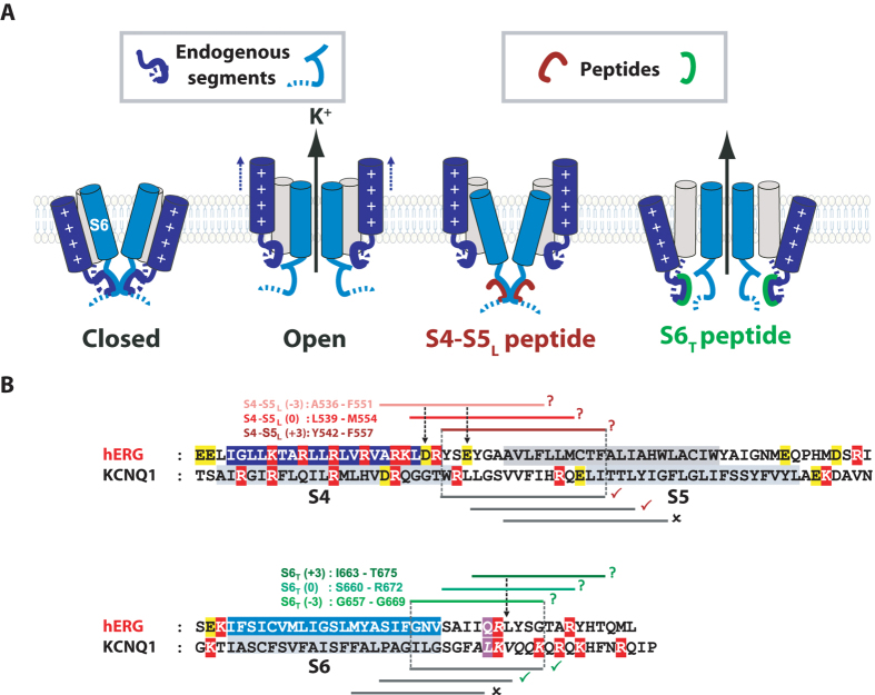
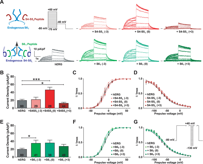
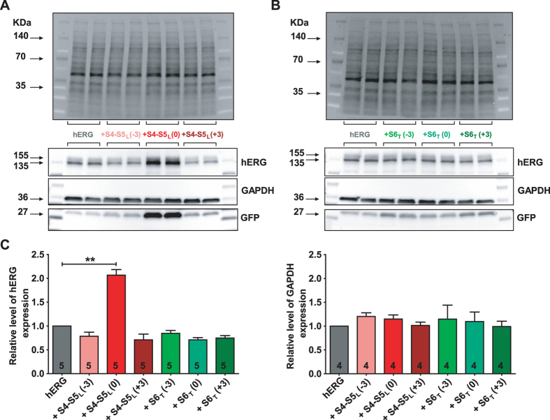
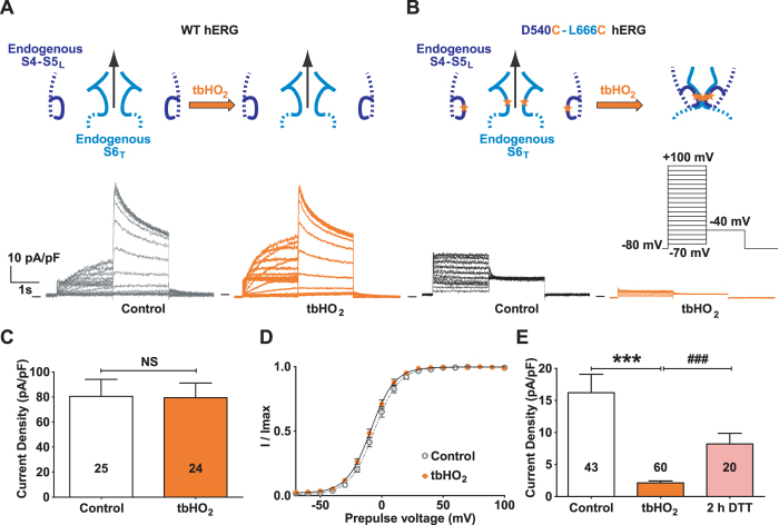
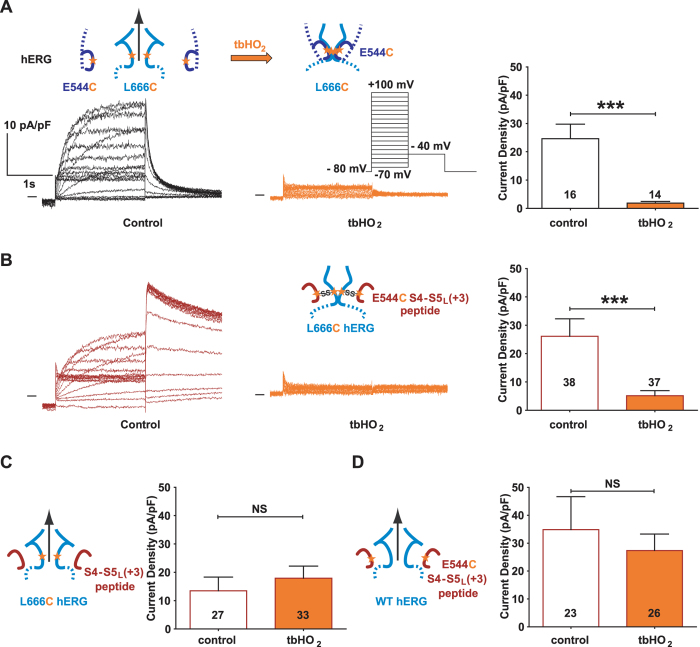
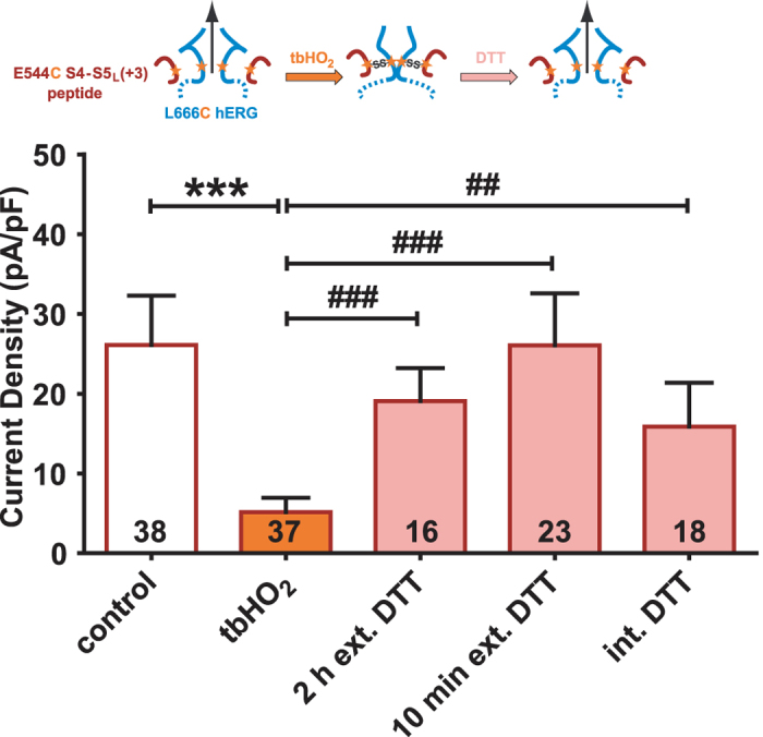
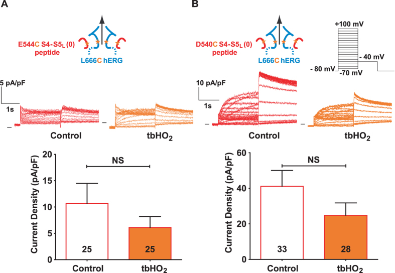
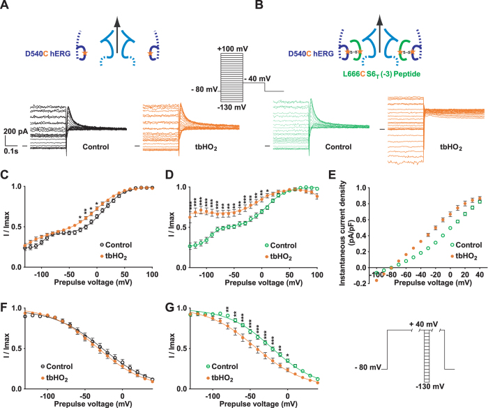
Delayed-rectifier potassium channels (hERG and KCNQ1) play a major role in cardiac repolarization. These channels are formed by a tetrameric pore (S5-S6) surrounded by four voltage sensor domains (S1-S4). Coupling between voltage sensor domains and the pore activation gate is critical for channel voltage-dependence. However, molecular mechanisms remain elusive. Herein, we demonstrate that covalently binding, through a disulfide bridge, a peptide mimicking the S4-S5 linker (S4-S5L) to the channel S6 C-terminus (S6T) completely inhibits hERG. This shows that channel S4-S5L is sufficient to stabilize the pore activation gate in its closed state. Conversely, covalently binding a peptide mimicking S6T to the channel S4-S5L prevents its inhibiting effect and renders the channel almost completely voltage-independent. This shows that the channel S4-S5L is necessary to stabilize the activation gate in its closed state. Altogether, our results provide chemical evidence that S4-S5L acts as a voltage-controlled ligand that binds S6T to lock the channel in a closed state, elucidating the coupling between voltage sensors and the gate in delayed rectifier potassium channels and potentially other voltage-gated channels.


Conflict of interest statement

The authors declare that they have no competing interests.

Figures

Figure 1
Figure 1
Hypothetical ligand/receptor model. Alignment used to design S4-S5L and S6T peptides. (A) Scheme of the hypothetical ligand/receptor model in which S4-S5L (deep blue) binds to S6T (light blue) to stabilize the channel in a closed state. Upon membrane depolarization, S4 pulls S4-S5L out of the S6T receptor, allowing channel opening. The S4-S5L peptide (red) mimics endogenous S4-S5L, locking the channel in its closed conformation. Contrarily, S6T peptide (green) binds to the endogenous S4-S5L and limits its locking effect, leading to channel up-modulation. (B) Alignment used to design hERG peptides from previously identified KCNQ1 S4-S5L and S6T peptides (based on the multiple alignment obtained using Clustal Omega, presented in Supplemental Fig. 4). In red are represented the basic residues, in yellow acidic residues, and in purple the position of the narrowest part of the bundle crossing, also named the gating residue (see methods). The color boxes represent the transmembrane segments. Grey lines represent the peptides tested in KCNQ1 while red lines and green lines represent the designed hERG S4-S5L and S6T peptides, respectively. A check sign (✓) indicates that the KCNQ1 S4-S5L peptide inhibits the channel (red) and that the KCNQ1 S6T peptide activates the channel (green).
Figure 2
Figure 2
S4-S5L (+3) peptide inhibits and S6T (−3) peptide activates hERG channels. (A) Representative, superimposed recordings of the WT hERG current in the absence (0.6 µg hERG plus 1.4 µg GFP plasmids) and in the presence of S4-S5L or S6T peptides (0.6 µg hERG plus 1.4 µg peptide plasmids). Left: schemes of the hypothetical effects of S4-S5L inhibiting or S6T activating peptide; activation voltage protocol used (one sweep every 8 s) located above the WT hERG currents; right: data from experiments performed in the presence of various S4-S5L or S6T peptides. (B) Mean hERG tail-current density at −40 mV after a prepulse at +60 mV in the presence of S4-S5L peptides. (C) Activation curve, obtained from tail currents using the protocol shown in A, in the presence of S4-S5L peptides (n = 21–65). (D) Inactivation curve in the presence of S4-S5L peptides (n = 6–24). Inset, Inactivation voltage protocol used (one sweep every 5 s, first pulse = 1 s, second pulse = 15 ms, third pulse = 0.5 s). (E) Through (G) same as B through D, in the presence of S6T peptides (F, n = 28–65; G, n = 15–24). *p < 0.1, ***p < 0.01 versus control hERG, Mann-Whitney test.
Figure 3
Figure 3
S4-S5L (0) peptide increases hERG channel expression. (A,B) western blot analysis of hERG protein expression in COS-7 cell lysates in the absence or presence of S4-S5L peptides (A) or S6T peptides (B). Top: stain-free image of total proteins. Bottom: western blot images of hERG, GAPDH, and GFP proteins. The three blots, realized on the same membrane, are cropped. Full-length blots of each tested protein are reported in Supplemental Fig. 1. (C) Histogram of normalized mean intensity of hERG (left) and GAPDH (right) bands in the absence and in the presence of various S4-S5L or S6T peptides. Band intensities are first normalized to the intensity of the corresponding stain-free membrane lane, and ratios are then normalized to control hERG condition. **p < 0.01 versus control hERG, Mann-Whitney test realized on non-normalized ratios.
Figure 4
Figure 4
Introduction of 2 cysteines in the S4-S5L and S6T regions of hERG (D540C-L666C hERG) locks the channel closed in oxidative conditions. (A) Representative, superimposed recordings of the WT hERG current (3.6 µg plasmid plus 0.4 µg GFP plasmids) after 2 h incubation in Tyrode without (control) or with 0.2 mM tbHO2 (tbHO2). (B) D540C-L666C hERG channels, same as in A (3.6 µg plasmid plus 0.4 µg GFP plasmids). Cartoons: introduction of a cysteine is symbolized by a star. (C) Mean WT hERG tail-current density at −40 mV after a prepulse at +100 mV. (D) Activation curve obtained from the tail currents, using the protocol shown in (B). (E) Mean D540C-L666C hERG tail-current density at −40 mV after a prepulse at +100 mV, after 2 h incubation in Tyrode without (control) or with 0.2 mM tbHO2 (tbHO2), or after 2 h incubation in 10 mM DTT following tbHO2 incubation (2 h DTT). ***p < 0.001 versus control and ###p < 0.001 versus tbHO2, Mann-Whitney test.
Figure 5
Figure 5
A cysteine disulfide bond reinforces the effect of the S4-S5L (+3) peptide, leading to full inhibition of the channel. (A) left, representative, superimposed recordings of the E544C-L666C hERG current (3.6 µg E544C-L666C hERG plasmid plus 0.4 µg GFP plasmids) and right, mean tail-current density at −40 mV after a prepulse at +100 mV after 2 h incubation in Tyrode without (control) or with 0.2 mM tbHO2 (tbHO2), both using the voltage protocol shown in inset. (B) left, representative, superimposed recordings of the single mutant L666C hERG current in the presence of E544C S4-S5L (+3) peptide (1 µg L666C hERG plus 3 µg peptide plasmids) and right, mean tail-current density  measured in the same conditions as A. (C,D) Mean tail-current density in the presence of only one cysteine, i.e. L666C hERG +S4-S5L (+3) peptide (C) or WT hERG +E544C S4-S5L (+3) peptide (D). ***p < 0.001 versus control, Mann-Whitney test.
Figure 6
Figure 6
hERG inhibition provoked by E544C S4-S5L (+3) peptide covalent binding to L666C mutant channel is reversible. Mean hERG tail-current density at −40 mV after a prepulse at +100 mV of L666C hERG channels in the presence of E544C S4-S5L (+3) peptide (1 µg L666C hERG plus 3 µg peptide plasmids) after 2 h incubation in Tyrode without (control) or with 0.2 mM tbHO2 (control and tbHO2, respectively, same results as in Fig. 5B), and after 2 h or 10 min incubation in 10 mM DTT following tbHO2 incubation, or after direct application of 10 mM DTT in the pipette tip, following tbHO2 incubation. ***p < 0.001 versus control, ##p < 0.01 and ###p < 0.001 versus tbHO2, Mann-Whitney test.
Figure 7
Figure 7
Unexpected hERG activation by S4-S5L (0) peptide is not reinforced by its covalent binding though a disulfide bond. (A) Top, representative, superimposed recordings of the L666C hERG current in the presence of E544C S4-S5L (0) peptide (1 µg L666C hERG plus 3 µg peptide plasmids) after 2 h incubation in Tyrode without (control) or with 0.2 mM tbHO2 (tbHO2), using the protocol shown in (B). Bottom, corresponding mean hERG tail-current density at −40 mV after a prepulse at +100 mV. (B) D540C S4-S5L (0) peptide same as in A.
Figure 8
Figure 8
A cysteine disulfide bond reinforces the effect of the activating S6T peptide, rendering the channel almost voltage independent. (A,B) Representative superimposed recordings of the single mutant D540C hERG current (A, 1 µg D540C hERG plus 3 µg GFP plasmids) and D540C hERG current in the presence of L666C S6T (−3) peptide (B, 1 µg D540C hERG plus 3 µg peptide plasmids) after 2 h incubation in Tyrode without (control) and with 0.2 mM tbHO2 (tbHO2), using the voltage protocol shown in inset. (C,D) Activation curve, with a double Boltzmann, obtained from the tail currents in the same conditions as A, in the absence (C) or presence of the L666C S6T (−3) peptide (D). (E) Maximum current density measured during the prepulse, using the protocol and conditions as in (A). (F,G) D540C hERG inactivation curve obtained using the protocol shown in right inset (same as in Fig. 2), in the absence (F) or presence of the L666C S6T (−3) peptide (G). *p < 0.05, **p < 0.01, ***p < 0.001, two way ANOVA with Bonferroni test.
Figure 9
Figure 9
hERG inhibiting (S4-S5L (+3)) and activating peptides (S6T (−3)) are aligned with KCNQ1 inhibiting and activating peptides. Same as in Fig. 1B, onto which the results obtained with hERG have been added. A check sign (✓) indicates that the S4-S5L peptide inhibits the channel and that the S6T peptide activates the channel.

References

    1. Jiang Y, et al. Crystal structure and mechanism of a calcium-gated potassium channel. Nature. 2002;417:515–522. doi: 10.1038/417515a. - DOI - PubMed
    1. Long SB, Campbell EB, Mackinnon R. Crystal structure of a mammalian voltage-dependent Shaker family K+ channel. Science. 2005;309:897–903. doi: 10.1126/science.1116269. - DOI - PubMed
    1. Grabe M, Lai HC, Jain M, Jan YN, Jan LY. Structure prediction for the down state of a potassium channel voltage sensor. Nature. 2007;445:550–553. doi: 10.1038/nature05494. - DOI - PubMed
    1. Lu Z, Klem AM, Ramu Y. Ion conduction pore is conserved among potassium channels. Nature. 2001;413:809–813. doi: 10.1038/35101535. - DOI - PubMed
    1. Lu Z, Klem AM, Ramu Y. Coupling between voltage sensors and activation gate in voltage-gated K+ channels. J Gen. Physiol. 2002;120:663–676. doi: 10.1085/jgp.20028696. - DOI - PMC - PubMed

Publication types

LinkOut - more resources