. 2017 Mar 9:7:44142.
doi: 10.1038/srep44142.

Magnetically controlled ferromagnetic swimmers

Affiliations

Magnetically controlled ferromagnetic swimmers

Joshua K Hamilton et al. Sci Rep. .

Abstract

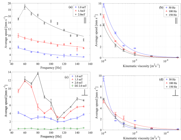
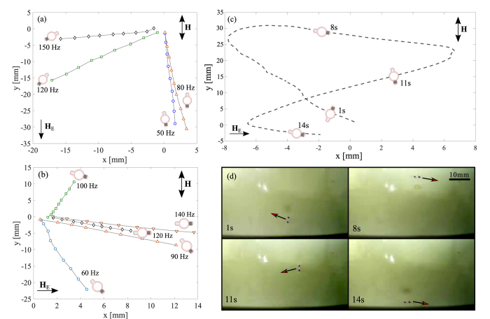
Microscopic swimming devices hold promise for radically new applications in lab-on-a-chip and microfluidic technology, diagnostics and drug delivery etc. In this paper, we demonstrate the experimental verification of a new class of autonomous ferromagnetic swimming devices, actuated and controlled solely by an oscillating magnetic field. These devices are based on a pair of interacting ferromagnetic particles of different size and different anisotropic properties joined by an elastic link and actuated by an external time-dependent magnetic field. The net motion is generated through a combination of dipolar interparticle gradient forces, time-dependent torque and hydrodynamic coupling. We investigate the dynamic performance of a prototype (3.6 mm) of the ferromagnetic swimmer in fluids of different viscosity as a function of the external field parameters (frequency and amplitude) and demonstrate stable propulsion over a wide range of Reynolds numbers. We show that the direction of swimming has a dependence on both the frequency and amplitude of the applied external magnetic field, resulting in robust control over the speed and direction of propulsion. This paves the way to fabricating microscale devices for a variety of technological applications requiring reliable actuation and high degree of control.


Conflict of interest statement

The authors declare no competing financial interests.

Figures

Figure 1
Figure 1. Fabrication and characteristic information.
(a) Schematic diagram showing the geometry of the modelled ferromagnetic swimmer. The model comprises of two magnetic beads of different size and anisotropic properties connected with an elastic link with zero volume. The larger bead (radius R1) has a magnetic moment (m1) that follows the applied magnetic field. The smaller bead (R2 = R1/2) has a fixed hard magnetic moment (m2). (b) Fabrication of the device. (1) The particles are placed into a brass mould and aligned using an external magnetic field. (2) Liquid elastomer fills the mould (0.5 mm deep) and is left to cure. (3) The final device. (Dimensions: overall length 3.6 mm, particle edge to edge separation of 1.6 mm (2.2 mm centre to centre), hard particle cubic (0.6 × 0.6 × 0.45 mm), soft particle cylindrical (0.7 mm long, diameter 0.5 mm)). (c) Force-extension curve of the silicone rubber link, which is approximately linear over the relevant strain range with an effective spring constant of (1.67 ± 0.08) × 10−2 N m−1 (d) Magnetic hysteresis loops for the hard and soft particles (blue and red, respectively). The magnetic moment of the hard and soft ferromagnetic particles at 2.0 mT are 1.39 × 10−1 emu and 2.45 × 10−2 emu, respectively. (e) The experimental apparatus, consisting of a signal generator and power amplifier (to power the oscillating magnetic field) and a coil system, supplying a field strength of 0.5–2.5 mT. The devices are placed at the fluid-air interface in a Petri dish and observed by a video camera.
Figure 2
Figure 2. Speed dependencies on external factors.
(a) Average speed as a function of frequency in water (kinematic viscosity v = 1 × 10−6 m2 s−1) and coil system parallel to the Earth’s magnetic field, at different external magnetic field strengths: 1.0 mT (blue circles), 1.5 mT (red triangles), and 2.0 mT (black squares). The solid lines are lines of best fit (see text). (b) Average speed as a function of viscosity (coil system parallel to the Earth’s magnetic field) with an external field strength of 1.5 mT at different frequencies; 50 Hz (blue circles), 100 Hz (red triangles), and 150 Hz (black squares). The lines are best fits. (c) Average speed as a function of frequency in water (kinematic viscosity v = 1 × 10−6 m2 s−1) and coil system perpendicular to the Earth’s magnetic field, at different external magnetic field strengths: 1.0 mT (blue circles), 1.5 mT (red triangles), 2.0 mT (black squares) and a device (D2) with an increased particle edge to edge separation of 2.4 mm (3 mm centre to centre) at 2.0 mT (green diamonds). The lines are guides to the eye only. (d) Average speed as a function of viscosity (coil system perpendicular to the Earth’s magnetic field) with an external field strength of 1.5 mT at different frequencies; 50 Hz (blue circles), 100 Hz (red triangles), and 150 Hz (black squares). The lines are best fits. The error bars on all plots represent the mean squared error in the speed calculated over a 20 second video at 30 fps.
Figure 3
Figure 3. Directional control using external factors.
Effects of the frequency and amplitude of the applied field on the direction of migration. The direction of the applied magnetic field, H, and the Earth’s magnetic field, HE (~0.02 mT) are indicated. (a) Direction of motion as a function of frequency at 2.0 mT for a parallel alignment between H and HE. The mean orientation of the swimmer is shown schematically for each frequency. The final point on each trajectory is at 1.9 seconds. (b) Direction of motion as a function of frequency at 2.0 mT for a perpendicular alignment between H and HE. The mean orientation of the swimmer is shown schematically for each frequency. The final point on each trajectory is at 1.9 seconds. (c) A figure of eight trajectory produced by varying both the frequency and amplitude (Supplementary Movie 1). The four sketches of the device show its orientation at the respective time points. (d) Still frames showing the direction of propagation at four different time points.

Similar articles

Cited by

References

    1. Purcell E. M. Life at low Reynolds number. Am. J. Phys. 45, 3–11 (1977).
    1. Shapere A. & Wilczek F. Geometry of self-propulsion at low Reynolds number. J. Fluid Mech. 198, 557 (1989).
    1. Lauga E. & Powers T. R. The hydrodynamics of swimming microorganisms. Reports Prog. Phys. 72, 96601 (2009).
    1. Najafi A. & Golestanian R. Simple swimmer at low Reynolds number: Three linked spheres. Phys. Rev. E - Stat. Nonlinear, Soft Matter Phys. 69 (2004). - PubMed
    1. Najafi A. & Zargar R. Two-sphere low-Reynolds-number propeller. Phys. Rev. E - Stat. Nonlinear, Soft Matter Phys. 81, 1–4 (2010). - PubMed

Publication types

LinkOut - more resources