. 2017 Apr 4;25(4):663-670.e3.
doi: 10.1016/j.str.2017.02.005. Epub 2017 Mar 9.

A Fast and Effective Microfluidic Spraying-Plunging Method for High-Resolution Single-Particle Cryo-EM

Affiliations

A Fast and Effective Microfluidic Spraying-Plunging Method for High-Resolution Single-Particle Cryo-EM

Xiangsong Feng et al. Structure. .

Abstract

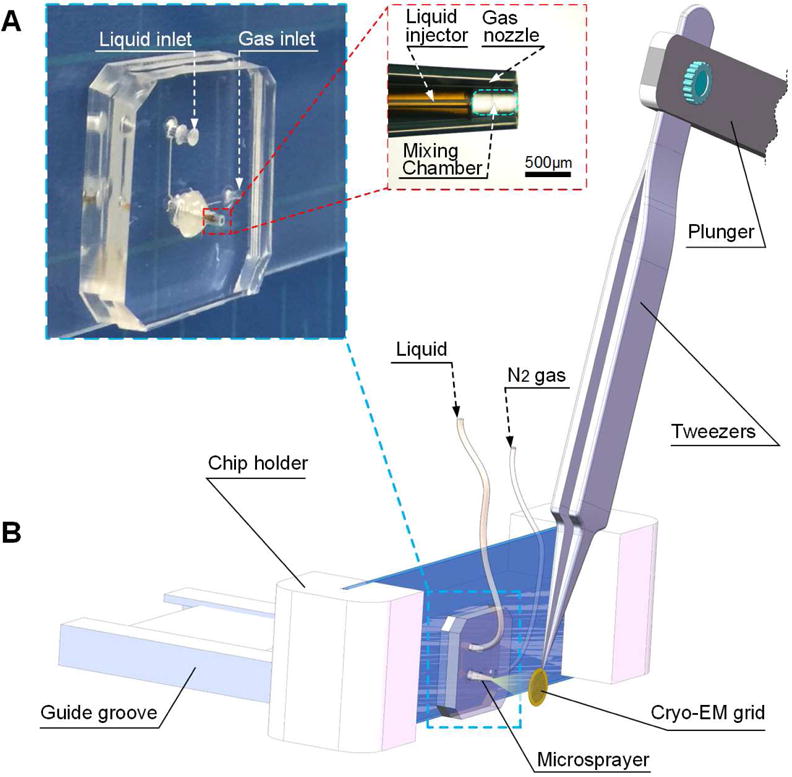
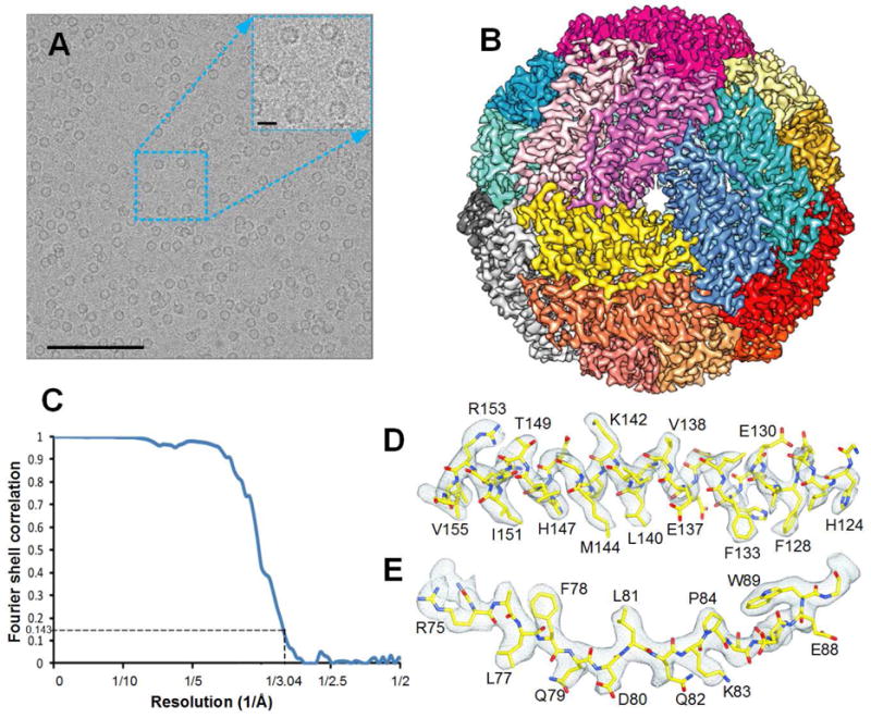
We describe a spraying-plunging method for preparing cryoelectron microscopy (cryo-EM) grids with vitreous ice of controllable, highly consistent thickness using a microfluidic device. The new polydimethylsiloxane (PDMS)-based sprayer was tested with apoferritin. We demonstrate that the structure can be solved to high resolution with this method of sample preparation. Besides replacing the conventional pipetting-blotting-plunging method, one of many potential applications of the new sprayer is in time-resolved cryo-EM, as part of a PDMS-based microfluidic reaction channel to study short-lived intermediates on the timescale of 10-1,000 ms.

Keywords: EM grid preparation; PDMS-based microsprayer; apoferritin; ice thickness; time-resolved cryo-EM.


Conflict of interest statement

Competing financial interests

The authors declare no competing financial interests.

Figures

Figure 1
Figure 1
Design of the microsprayer chip and the schematic diagram of the experimental setup (A) Design of the microsprayer chip. The sprayer is composed of the liquid injector and gas nozzle with orifice diameters of 75 and 360 μm, respectively. The space between these two orifices is 500 μm long and forms the mixing chamber. The liquid is introduced into the microsprayer chip, issuing from the liquid injector as a cylindric liquid jet. Simultaneously, the nitrogen gas is fed into the chip, regulated by the gas nozzle as a co-flowing gas stream surrounding the liquid jet in the mixing chamber, which facilitates the atomization. (B) The experimental setup. The position of the tweezers shown is only one transient point of its trajectory (see Figure S1), with the cryo-EM grid in the process of intersecting the spray plume. For adjustment of the precise position of the microsprayer nozzle, the chip holder can be slid back and forth in the guide groove and the microsprayer chip can be slid up and down in the chip holder. Hence the solution in the form of droplets is sprayed onto the EM grid, which is then quickly plunged into the cryogen (see also Figure S1). The resulting grid bears thin blobs of vitreous ice where the droplets have impinged on the grid surface. See also Figure S1 and Supplemental movies.
Figure 2
Figure 2
Measurements of ice thickness of droplets sprayed on the EM-grid with the following settings: liquid flow rate 6 μL/s, gas pressure 16 psi and sprayer-grid distance 5 mm. (A) Half of a grid showing the droplet distribution and the droplet size. (B) Area marked cyan in (A), at 120× magnification, was used to find a set of squares (red boxes) with particle-collectible droplets for further imaging. (C), (D), (E) and (F) Four squares targeted in (B) were imaged at 550×. Droplets with vitreous ice (marked with orange) allowing collection of particles are visible in these squares. (D) Positions of holes covered with ice were randomly chosen for drilling tunnels (red crosses). (G) A series of tunnels were drilled into the ice at the tilt angle of −30°. Then the grid was tilted to +30°, and images of projections of the tunnels were acquired. See also Figure S2.
Figure 3
Figure 3
The ice distribution in the holes. (A) and (B) The ice thickness is different from the leading to the trailing side of each hole (blue arrows), which is different from grids obtained by the blotting method. (C) and (D) The ice is thinner on one side than the other side as indicated by the different lengths of the tunnels drilled on the two sides. The thicker ice region on each hole is marked in yellow, the thinner ones in blue. See also Figure S3.
Figure 4
Figure 4
(A) High-quality electron micrograph of apoferritin from equine spleen (SIGMA A3641. 7 mg/ml in PBS buffer, 0.2 μm filtered) sprayed onto cryo-EM holy carbon grid and collected using the FEI Polara microscope with a Gatan K2 Summit direct electron detection camera. Scale bars for the micrograph and magnified region are 1000 and 100 Å, respectively. (B) Cryo-EM structure of apoferritin at 3.0 Å resolution with each subunit color-coded. (C) The FSC curve for the final cryo-EM 3D reconstruction, generated with Relion 1.4. (D) and (E) Representative cryo-EM densities (grey mesh), superimposed on our atomic model (main chain in yellow) for different apoferritin domains. See also Figure S6.
Figure 5
Figure 5
Three α-helical segments from one subunit. (A) The cryo-EM density of long α-helical segment is shown in blue mesh. The model was docked with rigid-body fitting using Chimera first, then manually optimized by fitting in Coot. (B) Short α-helical segment near the N-terminus. Long-base amino acid arginine is well preserved (R5). (C) The additional density accounting for the hydroxyl group of the tyrosine side chain (Y164) is clearly seen compared to the side chain for phenylalanine (F166). See also Figure S6.

References

    1. Adrian M, Dubochet J, Lepault J, McDowall AW. Cryo-electron microscopy of viruses. Nature. 1984;308:32–36. - PubMed
    1. Angert I, Burmester C, Dinges C, Rose H, Schröder RR. Elastic and inelastic scattering cross-sections of amorphous layers of carbon and vitrified ice. Ultramicroscopy. 1996;63:181–192.
    1. Bartesaghi A, Merk A, Banerjee S, Matthies D, Wu X, Milne JL, Subramaniam S. 2.2 Å resolution cryo-EM structure of β-galactosidase in complex with a cell-permeant inhibitor. Science. 2015;348:1147–1151. - PMC - PubMed
    1. Berriman J, Unwin N. Analysis of transient structures by cryo-microscopy combined with rapid mixing of spray droplets. Ultramicroscopy. 1994;56:241–252. - PubMed
    1. Campbell MG, Veesler D, Cheng A, Potter CS, Carragher B. 2.8 Å resolution reconstruction of the Thermoplasma acidophilum 20S proteasome using cryo–electron microscopy. Elife. 2015;4:e06380. - PMC - PubMed

Publication types

MeSH terms