. 2017 Mar;16(1):3-10.
doi: 10.1097/BTF.0000000000000142. Epub 2016 Nov 17.

Rotational Osteotomy for Hallux Valgus. A New Technique for Primary and Revision Cases

Affiliations

Rotational Osteotomy for Hallux Valgus. A New Technique for Primary and Revision Cases

Pablo Wagner et al. Tech Foot Ankle Surg. 2017 Mar.

Abstract

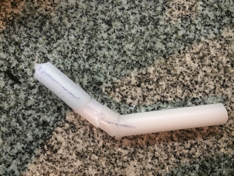
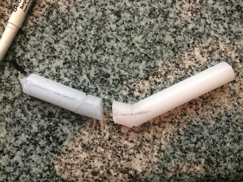
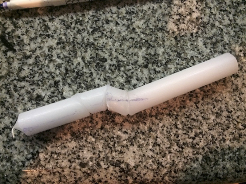
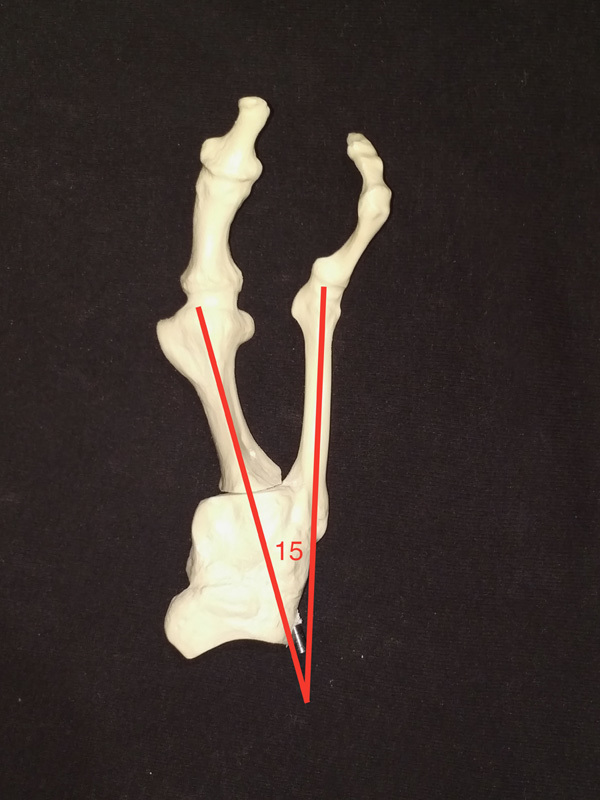
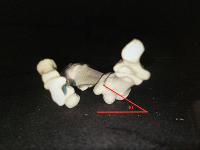
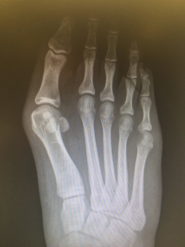
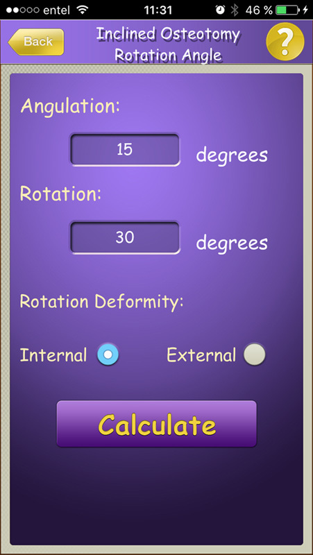
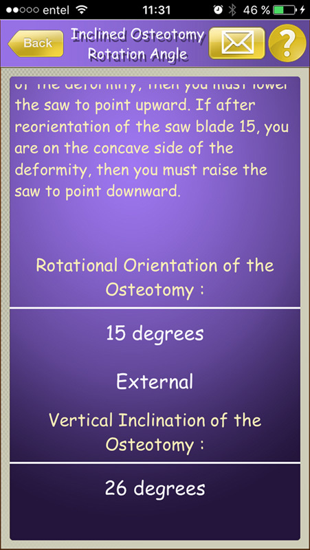
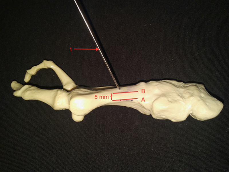
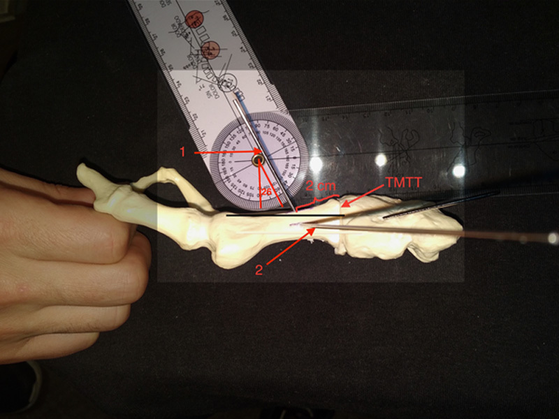
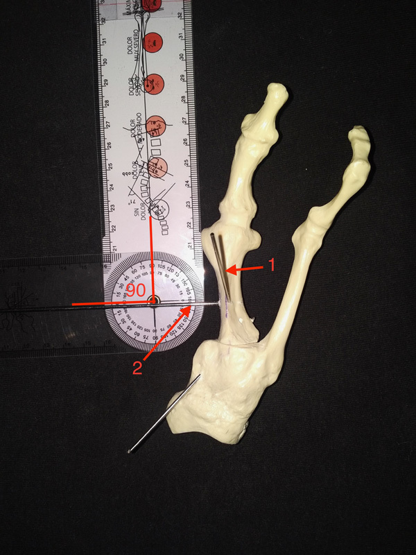
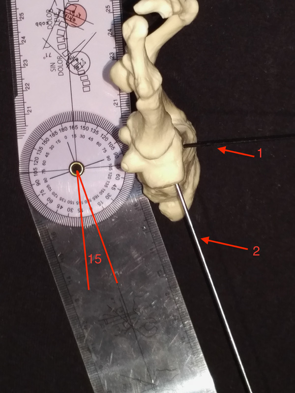
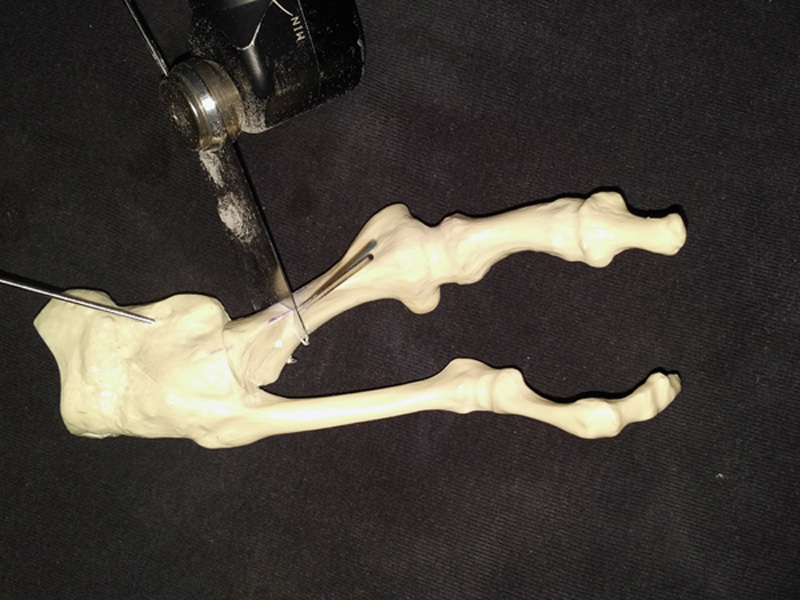
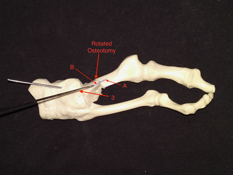
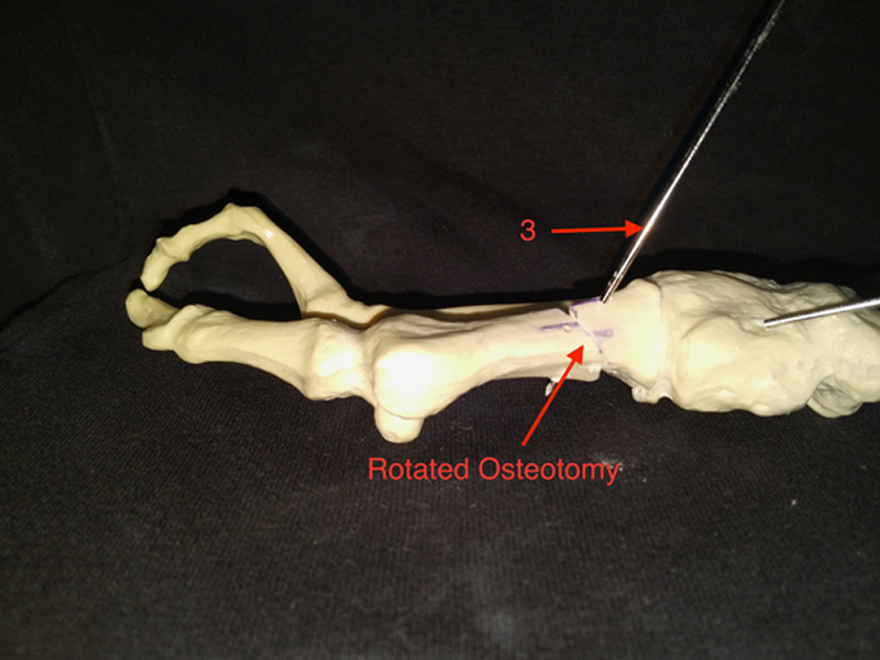
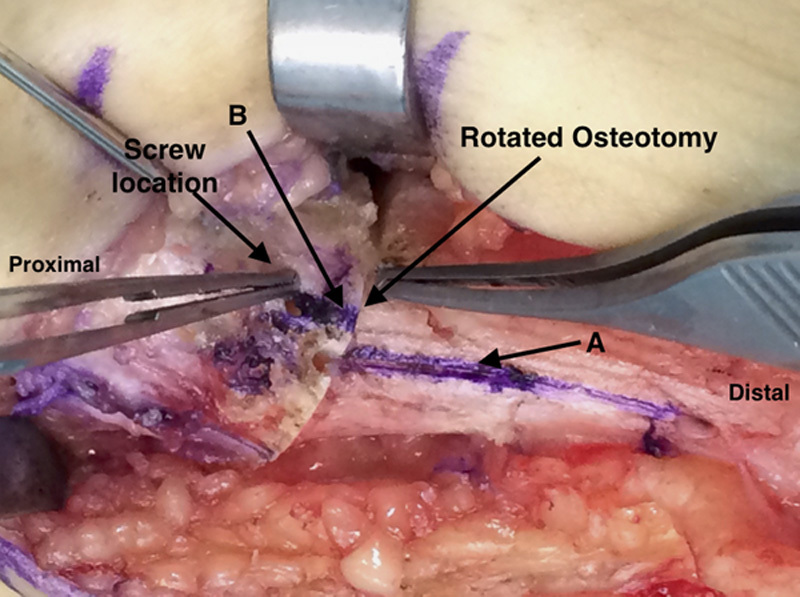
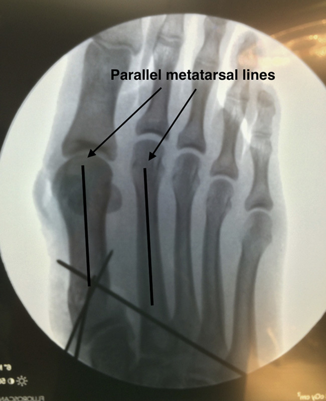
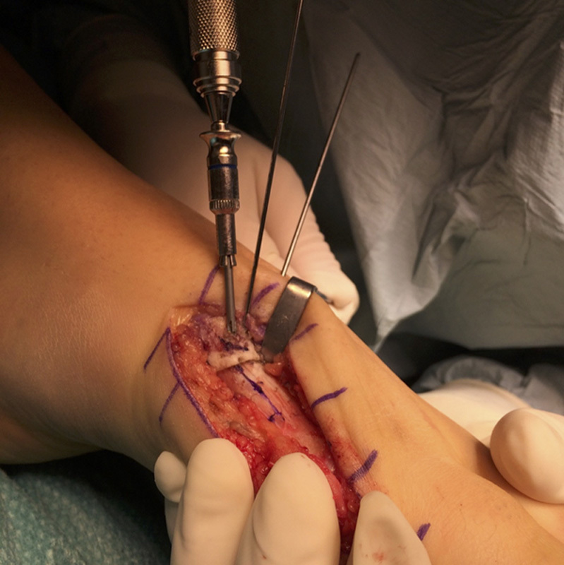
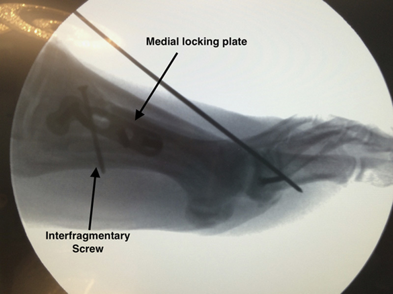
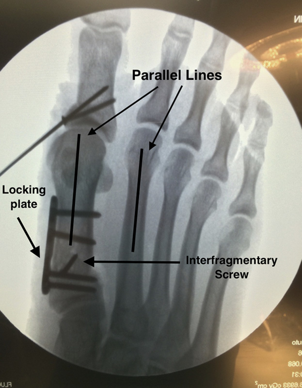
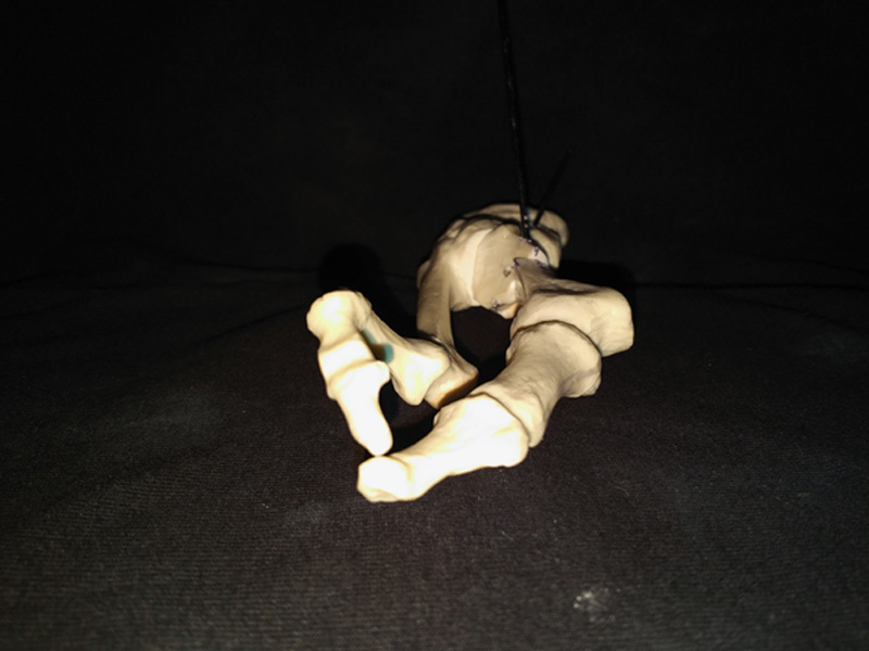
More than 200 different surgical techniques exist for hallux valgus (HV). Some of them are designed for mild, moderate, or severe deformities depending on their correction power. Nevertheless, they all correct only the coronal and/or sagittal plane deformity. Just a handful of them correct the known axial malrotation that exists in most HV cases. This malrotation is one possible factor that could be the source of recurrence of an operated HV as it has been described. We describe a new technique which simultaneously corrects the metatarsal internal rotation and varus deformity by rotating the metatarsal through an oblique plane osteotomy. This is performed with no bone wedge resection. Also, there is a broader bone surface contact than on a transverse proximal osteotomy. This technique is easy to remember and relatively simple to perform in primary and revision cases. The authors results show that it is as safe and effective as other procedures, with some advantages to be discussed.

Levels of evidence: Diagnostic Level 5. See Instructions for Authors for a complete description of levels of evidence.

Keywords: hallux valgus; osteotomy; rotational correction; surgical technique.


Conflict of interest statement

The authors declare no conflict of interest.

Figures

FIGURE 1
FIGURE 1
Candlewax precut.
FIGURE 2
FIGURE 2
Candlewax postcut.
FIGURE 3
FIGURE 3
Candlewax after rotating the distal part.
FIGURE 4
FIGURE 4
Model anteroposterior view, showing 15 degrees of intermetatarsal angle.
FIGURE 5
FIGURE 5
Model axial view, showing 30 degrees of internal rotation.
FIGURE 6
FIGURE 6
Foot anteroposterior x-ray showing a hallux valgus deformity, with 15 degrees of intermetatarsal angle.
FIGURE 7
FIGURE 7
Multiplier application: entering deformity parameters.
FIGURE 8
FIGURE 8
Multiplier application: osteotomy direction.
FIGURE 9
FIGURE 9
Model medial view, showing lines (A) and (B). Line (A) is midaxis medial line and (B) is 5 mm above (A). The numerical 1 is K-wire (1), showing its dorsal entry point.
FIGURE 10
FIGURE 10
Model medial view showing 26 degrees of angulation of K-wire (1), from distal-dorsal to plantar-proximal. The numerical 2 is K-wire (2). Both K-wires entry point is located 2 cm distal to the tarsometatarsal joint (TMTT).
FIGURE 11
FIGURE 11
Model anteroposterior view showing perpendicular orientation of K-wire (2) to the first metatarsal.
FIGURE 12
FIGURE 12
Model axial view showing K-wire (2) with 15 degrees of elevation from the ground.
FIGURE 13
FIGURE 13
Model anteroposterior view showing the saw cut following both K-wires orientation.
FIGURE 14
FIGURE 14
Model anteroposterior view after deformity correction, achieved through metatarsal external rotation. See how lines (A) and (B) match on the dorsum of the metatarsal. The numerical 3 indicates K-wire (3), which fixates the osteotomy.
FIGURE 15
FIGURE 15
Model medial view after deformity correction. Note that there is neither metatarsal elevation nor depression.
FIGURE 16
FIGURE 16
Medial in vivo foot view after osteotomy rotation. See how lines (A) and (B) match (there is a fake lines mismatch given the oblique direction of the picture). The proximal forceps shows the screw location. The distal forceps shows the osteotomy location.
FIGURE 17
FIGURE 17
Anteroposterior foot fluoroscopy, showing metatarsal deformity correction with both metatarsals shafts parallel.
FIGURE 18
FIGURE 18
Medial foot view, showing screw insertion.
FIGURE 19
FIGURE 19
Lateral foot fluoroscopy, showing interfragmentary screw and medial plate location. The wire seen in the figure is holding an Akin osteotomy, not discussed in this research.
FIGURE 20
FIGURE 20
Anteroposterior foot fluoroscopy, showing a medial metatarsal locking plate, the interfragmentary screw position, and the metatarsal deformity correction.
FIGURE 21
FIGURE 21
Model axial view, showing complete rotational correction.

References

    1. Trnka HJ. Osteotomies for hallux valgus correction. Foot Ankle Clin. 2005;10:15–33. - PubMed
    1. Deenik AR, de Visser E, Louwerens J-WK, et al. Hallux valgus angle as a main predictor for correction of hallux valgus. BMC Musculoskelet Disord. 2008;9:70. - PMC - PubMed
    1. Okuda R, Kinoshita M, Yasuda T, et al. Hallux valgus angle as a predictor of recurrence following proximal metatarsal osteotomy. J Orthop Sci. 2011;16:760–764. - PubMed
    1. Okuda R, Kinoshita M, Yasuda T, et al. Postoperative incomplete reduction of the sesamoids as a risk factor for recurrence of hallux valgus. J Bone Joint Surg Am. 2009;91:1637–1645. - PubMed
    1. Wagner E, Ortiz C. Osteotomy considerations in hallux valgus treatment improving the correction power. Foot Ankle Clin N Am. 2012;17:481–498. - PubMed