. 2017 Mar 1;4(1):33-48.
doi: 10.1089/soro.2016.0032.

Digital Morphing Wing: Active Wing Shaping Concept Using Composite Lattice-Based Cellular Structures

Affiliations

Digital Morphing Wing: Active Wing Shaping Concept Using Composite Lattice-Based Cellular Structures

Benjamin Jenett et al. Soft Robot. .

Abstract

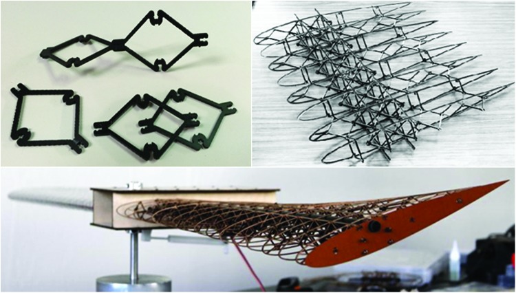
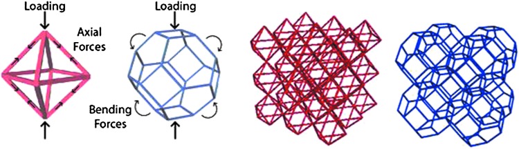
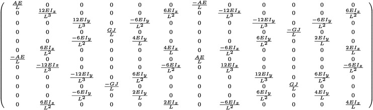
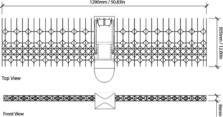
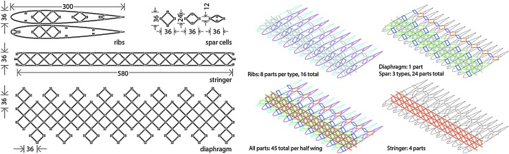
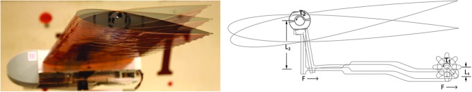
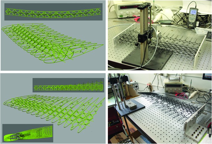
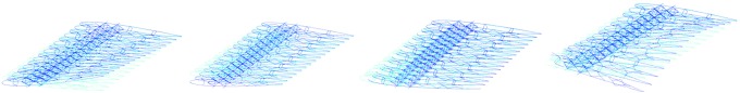
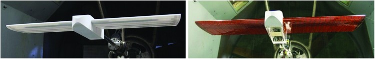
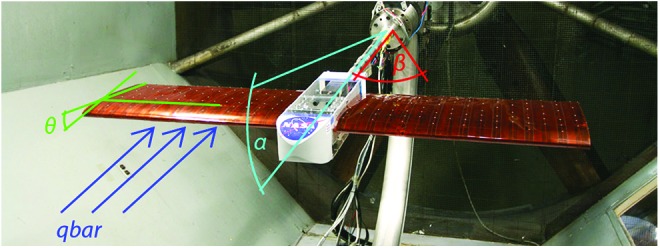
We describe an approach for the discrete and reversible assembly of tunable and actively deformable structures using modular building block parts for robotic applications. The primary technical challenge addressed by this work is the use of this method to design and fabricate low density, highly compliant robotic structures with spatially tuned stiffness. This approach offers a number of potential advantages over more conventional methods for constructing compliant robots. The discrete assembly reduces manufacturing complexity, as relatively simple parts can be batch-produced and joined to make complex structures. Global mechanical properties can be tuned based on sub-part ordering and geometry, because local stiffness and density can be independently set to a wide range of values and varied spatially. The structure's intrinsic modularity can significantly simplify analysis and simulation. Simple analytical models for the behavior of each building block type can be calibrated with empirical testing and synthesized into a highly accurate and computationally efficient model of the full compliant system. As a case study, we describe a modular and reversibly assembled wing that performs continuous span-wise twist deformation. It exhibits high performance aerodynamic characteristics, is lightweight and simple to fabricate and repair. The wing is constructed from discrete lattice elements, wherein the geometric and mechanical attributes of the building blocks determine the global mechanical properties of the wing. We describe the mechanical design and structural performance of the digital morphing wing, including their relationship to wind tunnel tests that suggest the ability to increase roll efficiency compared to a conventional rigid aileron system. We focus here on describing the approach to design, modeling, and construction as a generalizable approach for robotics that require very lightweight, tunable, and actively deformable structures.

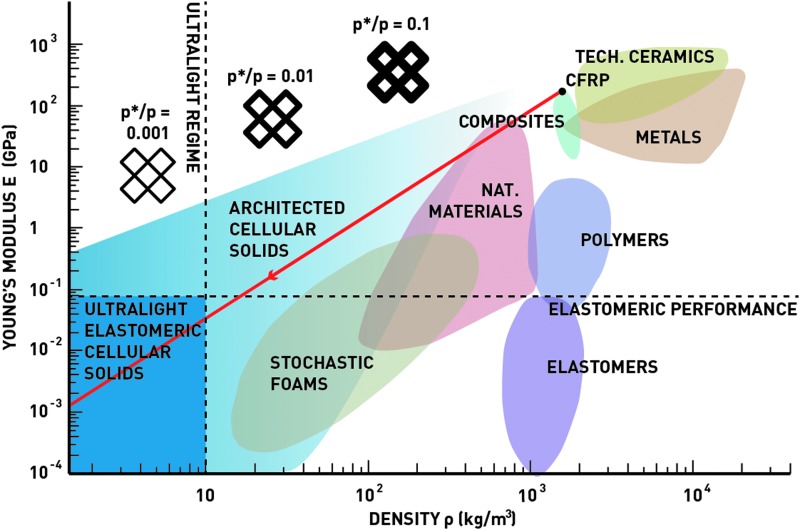
Keywords: discrete reconfigurable lattice assembly; morphing aerostructure; ultralight elastomeric cellular solid.


Conflict of interest statement

No competing financial interests exist.

Figures

<b>FIG. 1.</b>
FIG. 1.
Construction of shape-changing structures from discrete lattice building-block elements. Several elements are shown with two joined together (top–left); multiple part types are joined together to form part of the overall structure (top–right); an early prototype of the overall structures with shape-changing geometry exhibited (bottom).
<b>FIG. 2.</b>
FIG. 2.
Lattice geometry base cells and multi-cell assemblies. (Left) Base cell of cuboct lattice in red, Kelvin lattice in blue; (Right) Multi-cell assemblies of cuboct lattice in red, Kelvin lattice in blue.
<b>FIG. 3.</b>
FIG. 3.
Young's modulus versus density for engineering materials and cellular solids. Cellular solids allow the creation of unprecedented strength- and stiffness-per-weight structures by using high-performance constituent materials such as composites or technical ceramics, and by producing highly coordinated periodic frameworks. Below 10 kg/m3, these solids are considered “ultralight,” where their stiffness approaches that of elastomers, but with a significantly reduced weight.
<b>FIG. 4.</b>
FIG. 4.
Stiffness matrix for sample beam elements.
<b>FIG. 5.</b>
FIG. 5.
Stiffness matrix for beam elements with arbitrary orientation.
<b>FIG. 6.</b>
FIG. 6.
Results from torsional load simulation. Nodes on one end of the lattice are fixed in x, y, and z displacements, whereas loads are applied to nodes at the opposite end (scaled inversely by distance from the center to produce a constant torque about the central axis).
<b>FIG. 7.</b>
FIG. 7.
Results from bending load simulation. Nodes on both ends are fixed in the z direction (additional constraints applied to bottom end nodes to constrain rigid body movement), and constant loads are applied to nodes along the middle section.
<b>FIG. 8.</b>
FIG. 8.
Comparison of bending and torsional stiffness from simulation of heterogeneous lattices. Full cuboct structure is shown on the left, full Kelvin is on the right, and heterogeneous mixtures are in between.
<b>FIG. 9.</b>
FIG. 9.
Lattice parameters. Stretch dominated (left) and bending dominated (right). Lattice pitch (P), lattice strut length (l), strut thickness (t), and strut depth (d). Bounding box shown dashed.
<b>FIG. 10.</b>
FIG. 10.
Aero patch sizing method. The initial geometry is given to the VLM, which generates the aerodynamic forces that are then passed to the GFEM for static analysis. If the geometry that results from the GFEM converges, a cubic spline is used to create a lift coefficient for every millimeter. Those lift coefficients are then passed to Xfoil, which generates the pressure distribution around the airfoil for each section. GFEM, Galerkin Finite Element Method; VLM, vortex lattice method.
<b>FIG. 11.</b>
FIG. 11.
Wing skin patch size optimization results. The average patch pressure plotted against the angle of attack and patch size.
<b>FIG. 12.</b>
FIG. 12.
Wing skin patch size optimization results. Maximum displacement of an assumed thin plate with the average pressure applied from Figure 11.
<b>FIG. 13.</b>
FIG. 13.
Digital Morphing Wing Platform: main components, including structure, actuation, and instrumentation.
<b>FIG. 14.</b>
FIG. 14.
Overall wing platform dimension.
<b>FIG. 15.</b>
FIG. 15.
Building-block lattice part types. (Left) Part types with main dimensions in mm; (Right) Part groups and quantities shown for half wing.
<b>FIG. 16.</b>
FIG. 16.
Manual assembly technique of discrete building-block parts. (Left) Snap-fit features allow reversible joints and disassembly while still providing sufficient attachment to allow load transfer. (Right) Slot-type connections allow vertical assembly of intersecting planes and part types.
<b>FIG. 17.</b>
FIG. 17.
Wing mechanism actuation: (Left) Wind tunnel twist of ±10°. (Right) Wing mechanism design and mechanical advantage.
<b>FIG. 18.</b>
FIG. 18.
CFRP coupon testing results. As expected, all three orientations showed similar stiffness (with a variation of 2.6 GPa, or 9%), and the 45° sample had a slightly higher breaking strength. CFRP, carbon fiber-reinforced polymers.
<b>FIG. 19.</b>
FIG. 19.
Bench testing of wing structure. (Left) Visualization of simulated bending (top) and torsion (bottom) load cases. (Right) Bench testing of load application and deflection measurement for bending and torsion load cases.
<b>FIG. 20.</b>
FIG. 20.
Visualization of modal analysis results. (L to R) First torsion mode; Coupled bending-torsion mode; Pure bending mode; Second torsion mode. Light blue is initial geometry and dark blue is the mode shape vector. Results shown are produced using the Frame3DD library.
<b>FIG. 21.</b>
FIG. 21.
Simulation results of tendon diameter variation effects on flexural and torsional stiffness. (Left) Flexural stiffness and torsional stiffness over a varying cross-sectional diameter of the lattice tendons. (Right) Specific stiffnesses and specific torsional stiffness with the same variation.
<b>FIG. 22.</b>
FIG. 22.
Wind tunnel testing setup in NASA Langley 12-Foot Tunnel. (Left) Rigid wing model. (Right) Flexible wing model.
<b>FIG. 23.</b>
FIG. 23.
Wind tunnel test parameters. Dynamic pressure (qbar), wing tip twist (θ), angle of attack (α), and sideslip angle (β).

References

    1. Manti M, Hassan T, Passetti G, D'Elia N, Laschi C, Cianchetti M. A bioinspired soft robotic gripper for adaptable and effective grasping. Soft Robot 2015;2:107–116
    1. Zhang Y, Kim WS. Highly sensitive flexible printed accelerometer system for monitoring vital signs. Soft Robot 2014;1:132–135
    1. Marchese AD, Onal CD, Rus D. Autonomous soft robotic fish capable of escape maneuvers using fluidic elastomer actuators. Soft Robot 2014;1:75–87 - PMC - PubMed
    1. Gerdes J, Holness A, Perez-Rosado A, Roberts L, Greisinger A, Barnett E, et al. . Robo Raven: a flapping-wing air vehicle with highly compliant and independently controlled wings. Soft Robot 2014;1:275–288
    1. Trivedi D, Rahn CD, Kier WM, Walker ID. Soft robotics: Biological inspiration, state of the art, and future research. Appl Bionics Biomech 2008;5:99–117