. 2017 Mar 21:7:44901.
doi: 10.1038/srep44901.

High Temperature Near-Field NanoThermoMechanical Rectification

Affiliations

High Temperature Near-Field NanoThermoMechanical Rectification

Mahmoud Elzouka et al. Sci Rep. .

Abstract

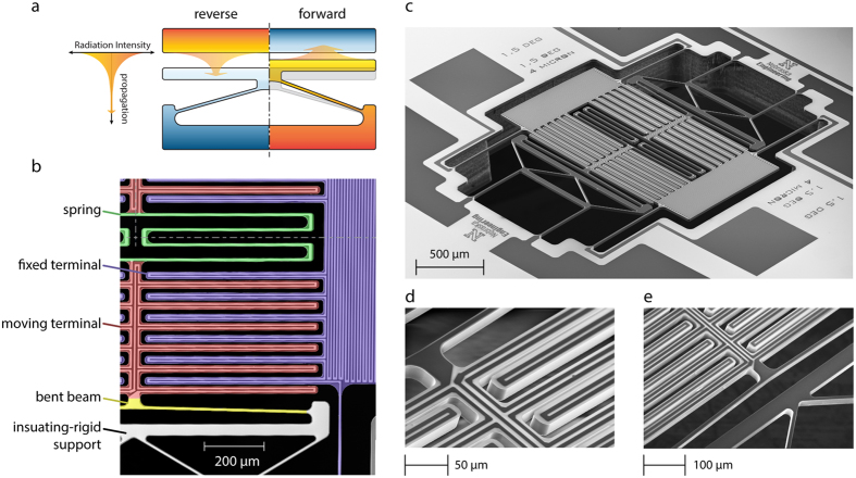
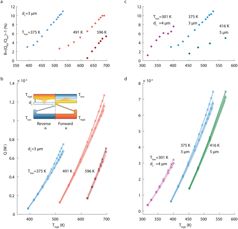
Limited performance and reliability of electronic devices at extreme temperatures, intensive electromagnetic fields, and radiation found in space exploration missions (i.e., Venus &Jupiter planetary exploration, and heliophysics missions) and earth-based applications requires the development of alternative computing technologies. In the pursuit of alternative technologies, research efforts have looked into developing thermal memory and logic devices that use heat instead of electricity to perform computations. However, most of the proposed technologies operate at room or cryogenic temperatures, due to their dependence on material's temperature-dependent properties. Here in this research, we show experimentally-for the first time-the use of near-field thermal radiation (NFTR) to achieve thermal rectification at high temperatures, which can be used to build high-temperature thermal diodes for performing logic operations in harsh environments. We achieved rectification through the coupling between NFTR and the size of a micro/nano gap separating two terminals, engineered to be a function of heat flow direction. We fabricated and tested a proof-of-concept NanoThermoMechanical device that has shown a maximum rectification of 10.9% at terminals' temperatures of 375 and 530 K. Experimentally, we operated the microdevice in temperatures as high as about 600 K, demonstrating this technology's suitability to operate at high temperatures.


Conflict of interest statement

The authors declare no competing financial interests.

Figures

Figure 1
Figure 1. Near-field NanoThermoMechanical rectifier.
(a) Near-field NanoThermoMechanical rectification concept. The rectifier is composed of a fixed terminal (at the top), a moving terminal (at the bottom), and a thermally-expandable structure (i.e., the v-shaped bent beam). The reverse and forward bias cases are represented in the left and the right halves of the sketch, respectively. The variable thickness arrow represents the decrease in thermal radiation intensity as radiation travels away from the heated surface. (b) False-color scanning electron micrograph of a quarter of the proof-of-concept microdevice, symmetric about the two perpendicular drawn symmetry lines. The microdevice incorporates 24 pairs of fixed and moving terminals in total, only 6 pairs are shown in (b). (c) scanning electron micrograph of the proof-of-concept microdevice. (d,e) are zoomed-in views showing the connection of the moving terminal to the folded-beam spring and the bent beam, respectively.
Figure 2
Figure 2. Thermal rectifier measured performance.
(a) Thermal rectification (R = Qfor/Qrev − 1) versus Thigh for a thermal rectifier device with initial separation gap (dc) of 3 μm. The thermal rectification is displayed for three different values of Tlow (375, 491 and 569 K). The first data set was collected while chuck temperature was set to 350 K, and the other two data sets were collected at a chuck temperature of 450 K. (b) The heat transfer rate across rectifier terminals in forward and reverse directions used to calculate the thermal rectification in a. The inset in b shows the assignment of Tlow and Thigh in forward and reverse directions, and the initial separation gap dc. Uncertainties in the measured heat transfer rates are represented by the shading around measurement points. (c) shows thermal rectification versus Thigh for three thermal rectifier devices with different initial separation gaps (3, 4 and 5 μm), at Tlow of 375, 301 and 416 K, respectively. Chuck temperature was set to 350, 296, and 400 K, respectively. (d) represents the heat transfer rates across rectifier terminals in forward and reverse directions used to calculate the thermal rectification in c.
Figure 3
Figure 3. Results of finite element analysis for the proof-of-concept microdevice.
(a,b) out-of-plane displacement for the bottom and top surfaces, respectively, unit on the scale is nanometers. (c) temperature distribution of the microdevice, unit on the scale is Kelvins.
Figure 4
Figure 4. Fabrication steps of the Near-field NanoThermoMechanical rectifier (drawings are not to-scale).
(a) Plain SOI wafer with a 20-μm thick device layer, and 0.5-μm buried silicon dioxide layer. (b) Thermal growth of 0.5-μm silicon dioxide layer, and plasma enhanced chemical vapor deposition of 1.5 μm of silicon dioxide. (c) Platinum microheater patterning with tantalum adhesion layer. (d) Reactive ion etching the (RIE) thermal silicon dioxide layer and then deep reactive ion etching (DRIE) of the silicon device layer to form the microdevice structure. (e) Etching of the backside of the substrate to release the microdevice structure.
Figure 5
Figure 5. Measurement of heat transfer rate across terminals.
(a) Measured heat dissipated in the fixed terminal (Qfix) versus temperature of the moving terminal (Tmov). Each set of Qfix and all other related measurements were conducted while the fixed terminal temperature (Tfix) was kept at a constant value. The two data sets correspond to two temperature values for Tfix: 375 and 530 K. (b) Measured heat dissipated in the moving terminal (Qmov) versus Tmov, for two different Tfix values of 375 and 530 K. Uncertainties were not plotted in a and b since they were low, less than 0.16% and 0.29% for Qfix and Qmov, respectively. (c) heat transfer from the fixed to the moving terminal (Qfix-mov) versus Tmov for the two different Tfix values. The dashed lines illustrate the heat transfer across terminals in forward and reverse directions for the set of temperature of 375 and 530 K. Uncertainties in the heat transfer rates are represented by the shaded area around the data points, with a maximum value of 2.74 × 10−5 W. (d) Heat losses from the moving terminal (Qloss,mov) versus Tmov, for the two different Tfix values. Uncertainties were not plotted here as they were low, less than 3.89 × 10−5 W. Uncertainty was calculated based on the technique reported in ref. , more details in Supplementary Information.

References

    1. Li N. et al.. Colloquium: Phononics: Manipulating heat flow with electronic analogs and beyond. Rev. Mod. Phys. 84, 1045–1066 (2012).
    1. Hunter G. W. et al.. High Temperature Electronics, Communications, and Supporting Technologies for Venus Missions. Electr. Eng. 8 (2006).
    1. Boll N. J., Salazar D., Stelter C. J., Landis G. A. & Colozza A. J. Venus high temperature atmospheric dropsonde and extreme-environment seismometer (HADES). Acta Astronaut. 111, 146–159 (2015).
    1. John D. & Cressler H. A. M. Extreme Environment Electronics (CRC Press, 2012).
    1. DOE/EIA-0035(2014-03). US Energy Flow., doi: https://flowcharts.llnl.gov/.

Publication types