

Accurate Determination of the Frequency Response Function of Submerged and Confined Structures by Using PZT-Patches†
- PMID: 28327501
- PMCID: PMC5375946
- DOI: 10.3390/s17030660
Accurate Determination of the Frequency Response Function of Submerged and Confined Structures by Using PZT-Patches†
Abstract
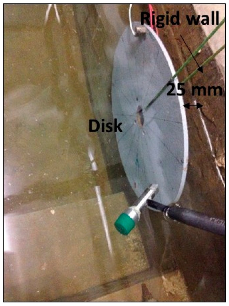
To accurately determine the dynamic response of a structure is of relevant interest in many engineering applications. Particularly, it is of paramount importance to determine the Frequency Response Function (FRF) for structures subjected to dynamic loads in order to avoid resonance and fatigue problems that can drastically reduce their useful life. One challenging case is the experimental determination of the FRF of submerged and confined structures, such as hydraulic turbines, which are greatly affected by dynamic problems as reported in many cases in the past. The utilization of classical and calibrated exciters such as instrumented hammers or shakers to determine the FRF in such structures can be very complex due to the confinement of the structure and because their use can disturb the boundary conditions affecting the experimental results. For such cases, Piezoelectric Patches (PZTs), which are very light, thin and small, could be a very good option. Nevertheless, the main drawback of these exciters is that the calibration as dynamic force transducers (relationship voltage/force) has not been successfully obtained in the past. Therefore, in this paper, a method to accurately determine the FRF of submerged and confined structures by using PZTs is developed and validated. The method consists of experimentally determining some characteristic parameters that define the FRF, with an uncalibrated PZT exciting the structure. These parameters, which have been experimentally determined, are then introduced in a validated numerical model of the tested structure. In this way, the FRF of the structure can be estimated with good accuracy. With respect to previous studies, where only the natural frequencies and mode shapes were considered, this paper discuss and experimentally proves the best excitation characteristic to obtain also the damping ratios and proposes a procedure to fully determine the FRF. The method proposed here has been validated for the structure vibrating in air comparing the FRF experimentally obtained with a calibrated exciter (impact Hammer) and the FRF obtained with the described method. Finally, the same methodology has been applied for the structure submerged and close to a rigid wall, where it is extremely important to not modify the boundary conditions for an accurate determination of the FRF. As experimentally shown in this paper, in such cases, the use of PZTs combined with the proposed methodology gives much more accurate estimations of the FRF than other calibrated exciters typically used for the same purpose. Therefore, the validated methodology proposed in this paper can be used to obtain the FRF of a generic submerged and confined structure, without a previous calibration of the PZT.
Keywords: PZT actuators; exciters; modal analysis; submerged structures.
Conflict of interest statement
The authors declare no conflict of interest.
Figures

References
-
- Ewins D.J. Modal Testing Theory and Practice. Research Studies Press; Letchworth, UK: 1984.
-
- Heylen W. Modal Analysis Theory and Testing. Katholieke Universiteit Leuven; Leuven, Belgium: 2007.
-
- Hearn G., Testa R.B. Modal analysis for damage detection in structures. J. Struct. Eng. 1991;117:3042–3063. doi: 10.1061/(ASCE)0733-9445(1991)117:10(3042). - DOI
-
- Hermans L., van der Auweraer H. Modal testing and analysis of structures under operational conditions: Industrial applications. Mech. Syst. Signal Process. 1999;13:193–216. doi: 10.1006/mssp.1998.1211. - DOI
-
- Egusquiza E., Valero C., Huang X., Jou E., Guardo A., Rodriguez C. Failure investigation of a large pump-turbine runner. Eng. Fail. Anal. 2012;23:27–34. doi: 10.1016/j.engfailanal.2012.01.012. - DOI
LinkOut - more resources
Full Text Sources
Other Literature Sources
Research Materials
Miscellaneous
