

Patient Posture Monitoring System Based on Flexible Sensors
- PMID: 28335385
- PMCID: PMC5375870
- DOI: 10.3390/s17030584
Patient Posture Monitoring System Based on Flexible Sensors
Abstract
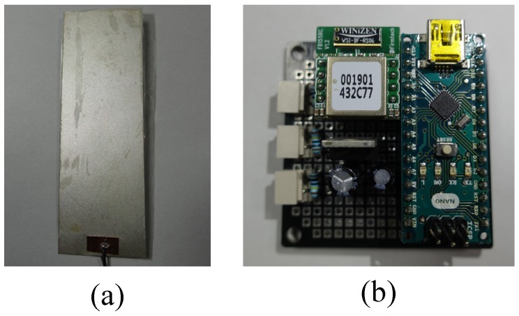
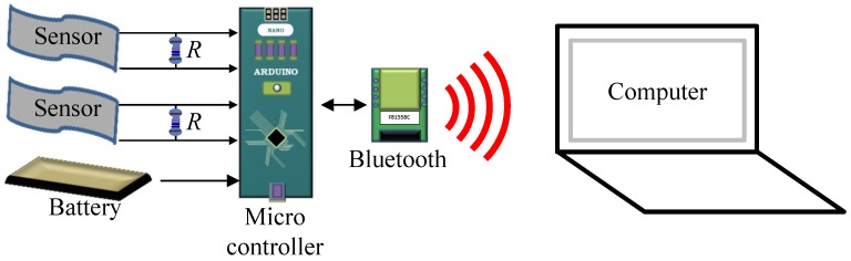
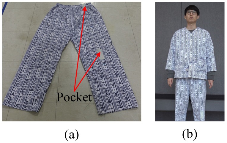
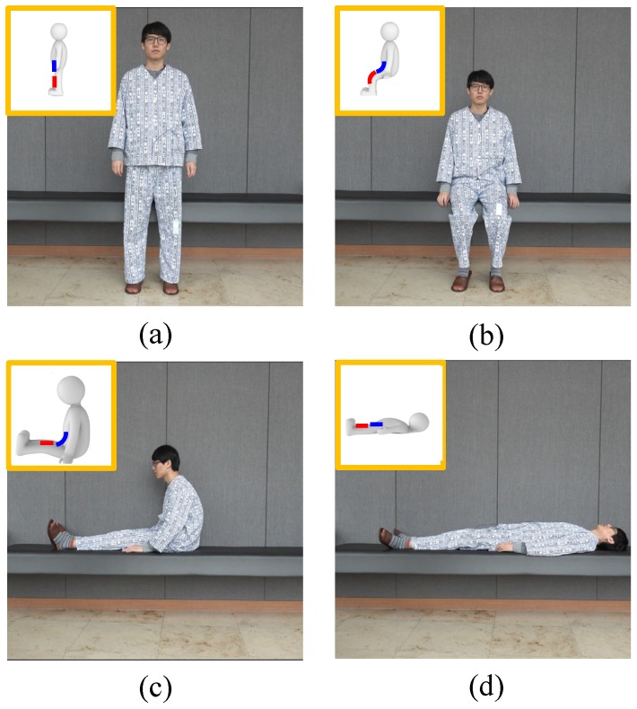
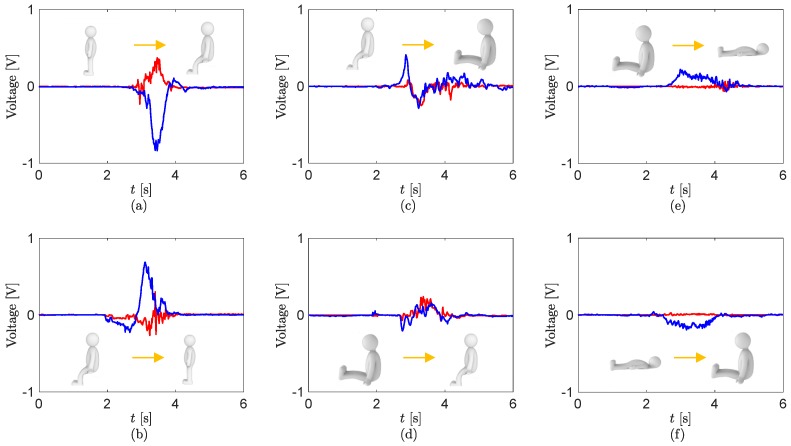
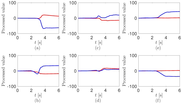
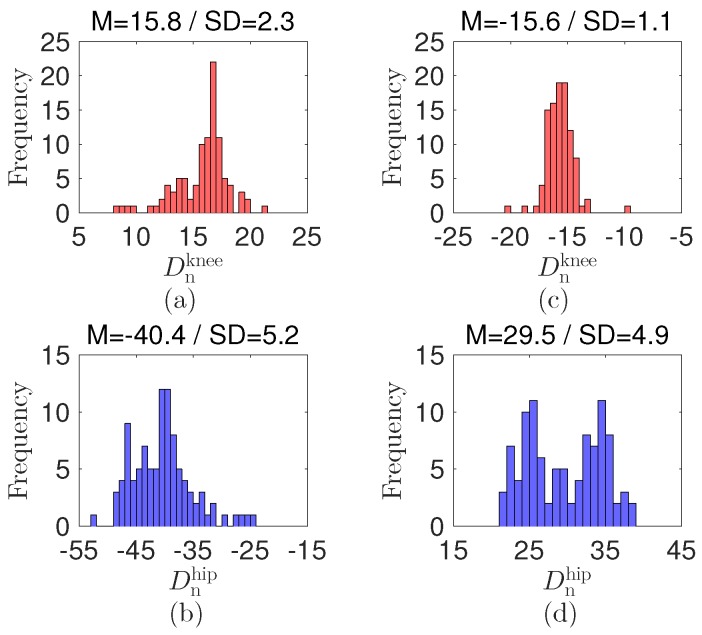
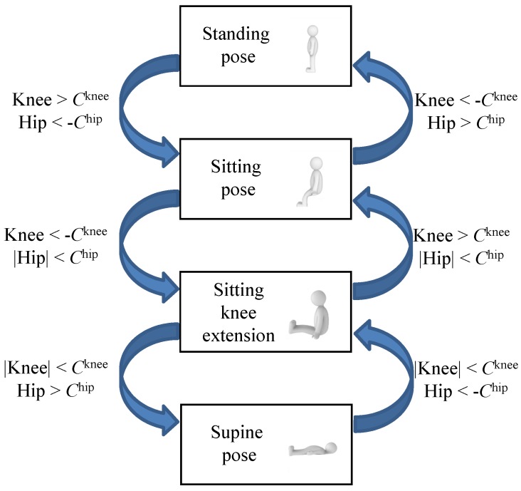
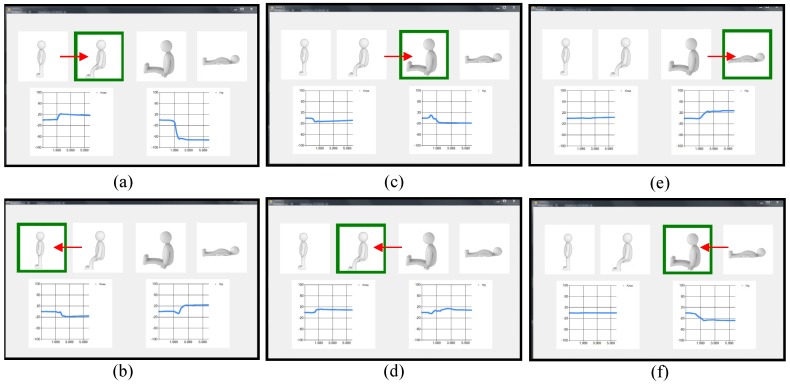
Monitoring patients using vision cameras can cause privacy intrusion problems. In this paper, we propose a patient position monitoring system based on a patient cloth with unobtrusive sensors. We use flexible sensors based on polyvinylidene fluoride, which is a flexible piezoelectric material. Theflexiblesensorsareinsertedintopartsclosetothekneeandhipoftheloosepatientcloth. We measure electrical signals from the sensors caused by the piezoelectric effect when the knee and hip in the cloth are bent. The measured sensor outputs are transferred to a computer via Bluetooth. We use a custom-made program to detect the position of the patient through a rule-based algorithm and the sensor outputs. The detectable postures are based on six human motions in and around a bed. The proposed system can detect the patient positions with a success rate over 88 percent for three patients.
Keywords: patient cloth; piezoelectric material; real-time monitoring; flexible sensor.
Conflict of interest statement
The authors declare no conflict of interest.
Figures
Similar articles
-
Patient cloth with motion recognition sensors based on flexible piezoelectric materials.Annu Int Conf IEEE Eng Med Biol Soc. 2017 Jul;2017:2410-2413. doi: 10.1109/EMBC.2017.8037342. Annu Int Conf IEEE Eng Med Biol Soc. 2017. PMID: 29060384
-
Flexible Piezoelectric Sensor-Based Gait Recognition.Sensors (Basel). 2018 Feb 5;18(2):468. doi: 10.3390/s18020468. Sensors (Basel). 2018. PMID: 29401752 Free PMC article.
-
A system for monitoring heart pulse, respiration and posture in bed.Biomed Sci Instrum. 2002;38:135-8. Biomed Sci Instrum. 2002. PMID: 12085590
-
The clinical applicability of sensor technology with body position detection to combat pressure ulcers in bedridden patients.Med Eng Phys. 2024 Feb;124:104096. doi: 10.1016/j.medengphy.2023.104096. Epub 2023 Dec 23. Med Eng Phys. 2024. PMID: 38418025
-
Wearable Sensors for Monitoring Human Motion: A Review on Mechanisms, Materials, and Challenges.SLAS Technol. 2020 Feb;25(1):9-24. doi: 10.1177/2472630319891128. Epub 2019 Dec 12. SLAS Technol. 2020. PMID: 31829083 Review.
Cited by
-
A Flexible Integrated Bending Strain and Pressure Sensor System for Motion Monitoring.Sensors (Basel). 2021 Jun 9;21(12):3969. doi: 10.3390/s21123969. Sensors (Basel). 2021. PMID: 34207521 Free PMC article.
-
Sweat permeable and ultrahigh strength 3D PVDF piezoelectric nanoyarn fabric strain sensor.Nat Commun. 2024 Apr 25;15(1):3509. doi: 10.1038/s41467-024-47810-7. Nat Commun. 2024. PMID: 38664454 Free PMC article.
-
Comparing Loose Clothing-Mounted Sensors with Body-Mounted Sensors in the Analysis of Walking.Sensors (Basel). 2022 Sep 1;22(17):6605. doi: 10.3390/s22176605. Sensors (Basel). 2022. PMID: 36081064 Free PMC article.
-
Flexible ferroelectric wearable devices for medical applications.iScience. 2020 Dec 29;24(1):101987. doi: 10.1016/j.isci.2020.101987. eCollection 2021 Jan 22. iScience. 2020. PMID: 33490897 Free PMC article. Review.
-
Posture Monitoring During Breastfeeding: Smart Underwear Integrated with an Accelerometer and Flexible Sensors.Sensors (Basel). 2024 Nov 29;24(23):7641. doi: 10.3390/s24237641. Sensors (Basel). 2024. PMID: 39686178 Free PMC article.
References
-
- Liang T., Yuan Y.J. Wearable medical monitoring systems based on wireless networks: A review. IEEE Sens. J. 2016;16:8186–8199. doi: 10.1109/JSEN.2016.2597312. - DOI
MeSH terms
LinkOut - more resources
Full Text Sources
Other Literature Sources
Medical
