. 2017 Apr 1;55(8):673-683.
doi: 10.1002/polb.24318. Epub 2017 Feb 18.

Ferroelectric switching and electrochemistry of pyrrole substituted trialkylbenzene-1,3,5-tricarboxamides

Affiliations

Ferroelectric switching and electrochemistry of pyrrole substituted trialkylbenzene-1,3,5-tricarboxamides

Xiao Meng et al. J Polym Sci B Polym Phys. .

Abstract

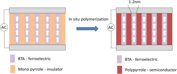
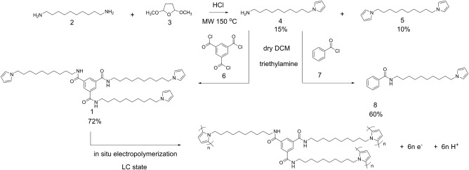
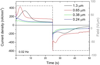
We explore a new approach to organic ferroelectric diodes using a benzene-tricarboxamide (BTA) core connected with C10 alkyl chains to pyrrole groups, which can be polymerized to provide a semiconducting ferroelectric material. The compound possesses a columnar hexagonal liquid crystalline (LC) phase and exhibits ferroelectric switching. At low switching frequencies, an additional process occurs, which leads to a high hysteretic charge density of up to ∼1000 mC/m2. Based on its slow rate, the formation of gas bubbles, and the emergence of characteristic polypyrrole absorption bands in the UV-Vis-NIR, the additional process is identified as the oxidative polymerization of pyrrole groups, enabled by the presence of amide groups. Polymerization of the pyrrole groups, which is essential to obtain semiconductivity, is limited to thin layers at the electrodes, amounting to ∼17 nm after cycling for 21 h. © 2017 Wiley Periodicals, Inc. J. Polym. Sci., Part B: Polym. Phys. 2017, 55, 673-683.

Keywords: electropolymerization; ferroelectric liquid crystal; interface; nanomaterials; polypyrrole.


Figures

Figure 1
Figure 1
Schematic representation of the intended ferroelectric diode design. After alignment in a ferroelectric columnar mesophase, pyrrole is polymerized into quasi‐1D polypyrrole channels that run parallel to the macrodipoles formed by the stacked BTA cores. [Color figure can be viewed at wileyonlinelibrary.com]
Scheme 1
Scheme 1
Synthesis of BTA‐C10‐pyrrole 1, C10‐bispyrrole 5, benzamide‐C10‐pyrrole 8, and electropolymerization of 1.
Figure 2
Figure 2
POM micrograph of BTA‐C10‐pyrrole (1) at 80 °C after cooling back from the isotropic temperature of 127 °C. Scale bar = 100 µm. [Color figure can be viewed at wileyonlinelibrary.com]
Figure 3
Figure 3
X‐ray scattering pattern of BTA‐C10‐pyrrole (1) measured at 80 °C.
Figure 4
Figure 4
(a) POM image of homeotropically aligned in electrode area (right) and nonaligned (left) BTA‐C10‐pyrrole (1), scale bar = 100 µm. (b) Schematic illustration of the molecular packing after homeotropic alignment. [Color figure can be viewed at wileyonlinelibrary.com]
Figure 5
Figure 5
(a) A single cycle of the voltage wave form used for probing the hysteretic polarization. (b) Current response to the triple triangular wave at 1 Hz. The maximum voltage corresponds to a field E = 53 V/µm. (c) The current associated with the polarization reversal (red) was obtained by subtracting the background current (green) from the raw signal (blue). (d) P–E hysteresis loops of BTA‐C10‐pyrrole 1 (black line, Al contacts, device thickness 850 nm, 53 V/µm), BTA‐C10‐alkyl (red line, Al contacts, device thickness 1400 nm, 53 V/µm), C10‐bispyrrole 5 (blue line, ITO contacts, device thickness 6500 nm, 53 V/µm), and benzamide‐C10‐pyrrole 8 (green line, ITO contacts, device thickness 6500 nm, 37 V/µm), at 80 °C, and 1 Hz. [Color figure can be viewed at wileyonlinelibrary.com]
Figure 6
Figure 6
(a) Current density as a function of time at 0.05 Hz of 1 showing two processes labeled 1 and 2. Blue line: raw signal, green line: background signal, red line: corrected signal. (b) Hysteretic charge density‐field hysteresis loops of 1 at 80 °C from 0.01 to 2 Hz (Al contacts, device thickness 850 nm, 53 V/µm). (c) Current density as a function of time at 0.05 Hz of 8 showing only a single peak associated with a high hysteretic charge density. Blue line: raw signal, green line: background signal, red line: corrected signal. (d) Hysteretic charge density‐field hysteresis loops of 8 at 80 °C from 0.01 to 2 Hz (ITO contacts, device thickness 6500 nm, 37 V/µm). [Color figure can be viewed at wileyonlinelibrary.com]
Figure 7
Figure 7
(a) UV–Vis–NIR spectrum of BTA‐C10‐pyrrole material in ITO–Al device after applying a cyclic bias for 2 h and subsequent etching of the Al electrode. (b) Polarized optical microscopy image of the BTA‐C10‐pyrrole material on ITO after removal of the Al electrode in both the active region (lower half) and the nonactive region (upper half) of the diode. Scale bar = 100 µm. [Color figure can be viewed at wileyonlinelibrary.com]
Figure 8
Figure 8
Current density as a function of time for BTA‐C10‐pyrrole/BTA‐C10‐alkyl mixture (80 wt % BTA‐C10‐pyrrole) thin films of different thickness in response to a 0.02 Hz block wave with an amplitude of 83 V/µm at 80 °C. [Color figure can be viewed at wileyonlinelibrary.com]
Figure 9
Figure 9
(a) Corrected current density as a function of time for BTA‐C10‐pyrrole thin films after different cycling times and (b) corresponding hysteretic charge density‐field loops. Black line: pristine, red line: after 30 min, green line: after 21 h of 1 upon cycling at 0.01 Hz, drive amplitude 53 V/µm. (c) P–E loops probed at normal (dashed line, 53 V/µm) and high field (solid line, 287 V/µm) at 2 Hz after cycling for 21 h at 53 V/µm. [Color figure can be viewed at wileyonlinelibrary.com]
Figure 10
Figure 10
Schematic illustration of ferroelectric switching and electrochemical reaction of BTA–pyrrole material under bias stress. (a) First, the amide dipoles are oriented by the electric field. (b) The negative charges of the dipoles reduce the electron injection barrier from the material into the electrode which facilitates the electrochemical oxidation of pyrrole. During pyrrole polymerization, protons are produced and a thin layer of polypyrrole is formed at the interface. The protons move to the opposite electrode by the electric field and reduce there to hydrogen gas. (c) During cycling, pyrrole oxidation takes place at both electrodes. (d) Multiple polypyrrole layers are formed upon cycling. [Color figure can be viewed at wileyonlinelibrary.com]

Similar articles

Cited by

References

    1. Horiuchi S., Tokura Y., Nat. Mater. 2008, 7, 357–366. - PubMed
    1. Naber R. C. G., Asadi K., Blom P. W. M., de Leeuw D. M., de Boer B., Adv. Mater. 2010, 22, 933–945. - PubMed
    1. Asadi K., de Leeuw D. M., de Boer B., Blom P. W. M., Nat. Mater. 2008, 7, 547–550. - PubMed
    1. Lee J., van Breemen A. J. J. M., Khikhlovskyi V., Kemerink M., Janssen R. A. J., Gelinck G. H., Sci. Rep. 2016, 6, 24407. - PMC - PubMed
    1. Kemerink M., Asadi K., Blom P. W. M., de Leeuw D. M., Org. Electron. 2012, 13, 147–152.