. 2017 May 13;375(2093):20160156.
doi: 10.1098/rsta.2016.0156.

The molten glass sewing machine

Affiliations

The molten glass sewing machine

P-T Brun et al. Philos Trans A Math Phys Eng Sci. .

Abstract

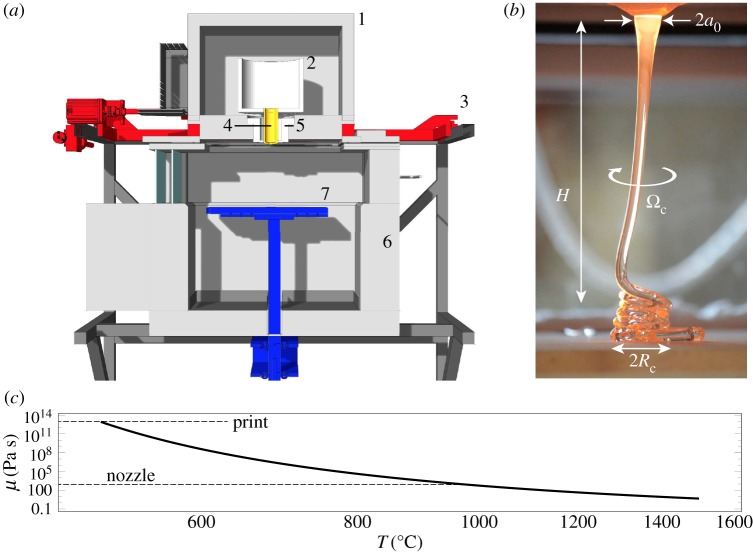
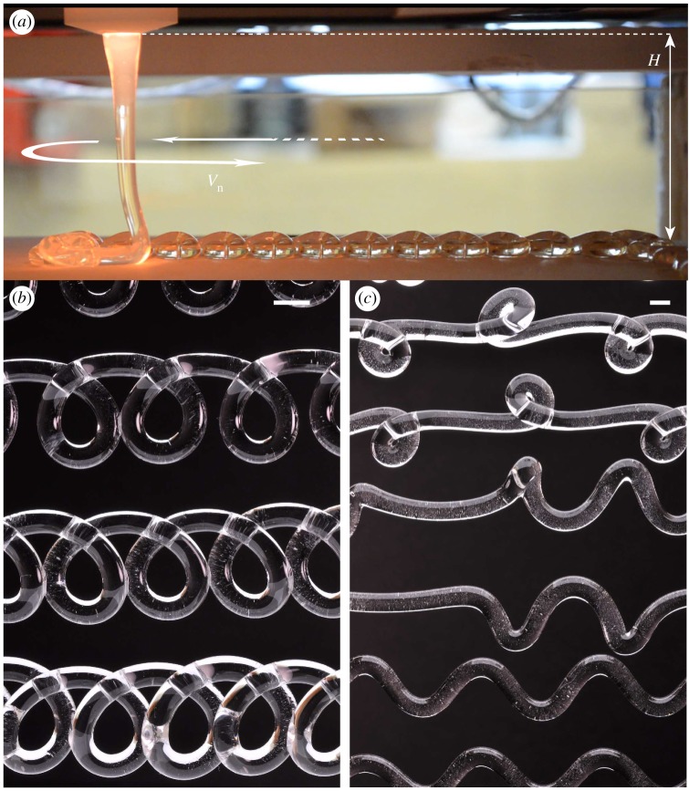
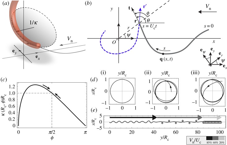
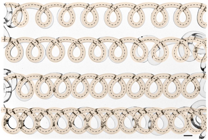
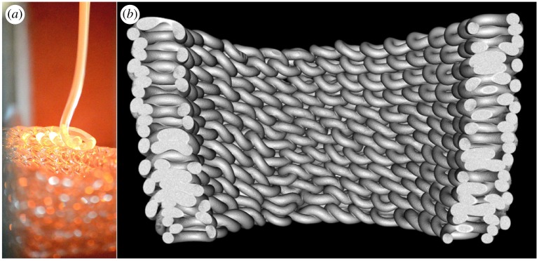
We present a fluid-instability-based approach for digitally fabricating geometrically complex uniformly sized structures in molten glass. Formed by mathematically defined and physically characterized instability patterns, such structures are produced via the additive manufacturing of optically transparent glass, and result from the coiling of an extruded glass thread. We propose a minimal geometrical model-and a methodology-to reliably control the morphology of patterns, so that these building blocks can be assembled into larger structures with tailored functionally and optically tunable properties.This article is part of the themed issue 'Patterning through instabilities in complex media: theory and applications'.

Keywords: coiling; glass; honey; instability; pattern; viscous thread.


Figures

Figure 1.
Figure 1.
Experimental set-up. (a) Schematic view of the 3D printer, which comprises (1) the crucible kiln, (2) crucible, (3) xy-motion stage, (4) the nozzle, (5) nozzle kiln, (6) annealing kiln, (7) ceramic build plate and z-axis motion. (b) Thread of initial radius a0 falling from a distance H onto the print plate. The thread accelerates under the action of gravity so that its radius decreases during the fall and buckles under its own weight. The coiling motion is characterized by the radius Rc and frequency Ωc. (c) Dynamic viscosity, μ, of the glass thread plotted as a function of temperature as prescribed in equation (2.1), using data from [23]. (Online version in colour.)
Figure 2.
Figure 2.
The molten glass sewing machine. (a) The nozzle is advected horizontally at speed Vn. Instead of the expected straight line, the system generates a variety of patterns; (b) translated coils and (c) alternated loops and meanders. Scale bars are 5 mm in length in (b) and (c). (Online version in colour.)
Figure 3.
Figure 3.
(a) Sketch of the heel-like structure of the thread in the vicinity of the printing plate. Its shape is approximated by a fraction of a circle with radius 1/κ. (b) Kinematics of the problem describing the position of the contact point, r, and pattern, q, forming at speed Uc while being advected at speed Vn. t and r′, respectively, denote the tangent to the pattern in the laboratory frame and the tangent to the fictitious trajectory of the contact point in the frame of the nozzle. (c) The thread’s curvature κ is assumed to be a function of r and ϕ. Shown here is dependence in ϕ for r=Rc. (d) Integration of the reduced model (3.5) with Vn=0 for (i) r(0)=1,ϕ(0)=π/2, (ii) r(0)=0.5,ϕ(0)=π/2 and (iii) r(0)=1.2,ϕ(0)=3π/4 displaying the stability of the base solution (i). (e) Result of the integration of equation (3.5), where Vn is a piecewise function of time as indicated in the legend. Coils, alternated loops and meanders are recovered. (Online version in colour.)
Figure 4.
Figure 4.
Comparison between theoretical and experimental results. Experimental photographs of the glass pattern obtained with a nozzle of radius a0= 5 mm, height of fall H=100 mm and nozzle speed Vn= [9,8,7,6] mm s−1 from top to bottom serves as a background of the image. It is compared with the numerical results obtained by integrating equation (3.5) using the values Rc=6.8 mm, Ωc=2π/1.62 s−1, so that Uc≃26 mm s−1, and the value of Vn corresponding to each row. The dotted line represents the centreline as predicted by theory, and the transparent orange lines are the result of reconstruction obtained giving adequate thickness to this line in order to best fit the pattern. The scale bar is 5 mm in length. (Online version in colour.)
Figure 5.
Figure 5.
Coiling patterns as building blocks. (a) Photograph of an experiment illustrating the structure progressively formed as the nozzle follows a circular printing path. (b) Computerized X-ray tomograph scan of the final structure. Each loop is roughly 15 mm in size. (Image credit: James Weaver.) (Online version in colour.)

References

    1. Audoly B, Pomeau Y. 2010. Elasticity and geometry: from hair curls to the non-linear response of shells. Oxford, UK: Oxford University Press.
    1. PM Reis. 2015. A perspective on the revival of structural (in)stability with novel opportunities for function: from buckliphobia to buckliphilia. J. Appl. Mech. 82, 111001 (10.1115/1.4031456) - DOI
    1. Fermigier M, Limat L, Wesfreid JE, Boudinet P, Quilliet C. 1992. Two-dimensional patterns in Rayleigh–Taylor instability of a thin layer. J. Fluid Mech. 236, 349–383. (10.1017/S0022112092001447) - DOI
    1. Cao Y, Hutchinson JW. 2012. From wrinkles to creases in elastomers: the instability and imperfection-sensitivity of wrinkling. Proc. R. Soc. A 468, 94–115. (10.1098/rspa.2011.0384) - DOI
    1. Kim JB, Kim P, Pégard NC, Oh SJ, Kagan CR, Fleischer JW, Stone HA, Loo Y-L. 2012. Wrinkles and deep folds as photonic structures in photovoltaics. Nat. Photon. 6, 327–332. (10.1038/nphoton.2012.70) - DOI

LinkOut - more resources