Decoding Network Structure in On-Chip Integrated Flow Cells with Synchronization of Electrochemical Oscillators
- PMID: 28387237
- PMCID: PMC5384074
- DOI: 10.1038/srep46027
Decoding Network Structure in On-Chip Integrated Flow Cells with Synchronization of Electrochemical Oscillators
Abstract
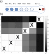
The analysis of network interactions among dynamical units and the impact of the coupling on self-organized structures is a challenging task with implications in many biological and engineered systems. We explore the coupling topology that arises through the potential drops in a flow channel in a lab-on-chip device that accommodates chemical reactions on electrode arrays. The networks are revealed by analysis of the synchronization patterns with the use of an oscillatory chemical reaction (nickel electrodissolution) and are further confirmed by direct decoding using phase model analysis. In dual electrode configuration, a variety coupling schemes, (uni- or bidirectional positive or negative) were identified depending on the relative placement of the reference and counter electrodes (e.g., placed at the same or the opposite ends of the flow channel). With three electrodes, the network consists of a superposition of a localized (upstream) and global (all-to-all) coupling. With six electrodes, the unique, position dependent coupling topology resulted spatially organized partial synchronization such that there was a synchrony gradient along the quasi-one-dimensional spatial coordinate. The networked, electrode potential (current) spike generating electrochemical reactions hold potential for construction of an in-situ information processing unit to be used in electrochemical devices in sensors and batteries.
Conflict of interest statement
The authors declare no competing financial interests.
Figures


Similar articles
-
Spatially organized dynamical states in chemical oscillator networks: synchronization, dynamical differentiation, and chimera patterns.PLoS One. 2013 Nov 15;8(11):e80586. doi: 10.1371/journal.pone.0080586. eCollection 2013. PLoS One. 2013. PMID: 24260429 Free PMC article.
-
Synchronization of three electrochemical oscillators: From local to global coupling.Chaos. 2018 Apr;28(4):045104. doi: 10.1063/1.5012520. Chaos. 2018. PMID: 31906643
-
Dynamics of electrochemical oscillators with electrode size disparity: asymmetrical coupling and anomalous phase synchronization.Phys Chem Chem Phys. 2011 Sep 14;13(34):15483-91. doi: 10.1039/c1cp21429b. Epub 2011 Aug 2. Phys Chem Chem Phys. 2011. PMID: 21808800
-
Microfabricated reference electrodes and their biosensing applications.Sensors (Basel). 2010;10(3):1679-715. doi: 10.3390/s100301679. Epub 2010 Mar 2. Sensors (Basel). 2010. PMID: 22294894 Free PMC article. Review.
-
Integrated electrochemical DNA biosensors for lab-on-a-chip devices.Electrophoresis. 2009 Oct;30(19):3386-97. doi: 10.1002/elps.200900319. Electrophoresis. 2009. PMID: 19802851 Review.
Cited by
-
Anti-phase collective synchronization with intrinsic in-phase coupling of two groups of electrochemical oscillators.Philos Trans A Math Phys Eng Sci. 2019 Dec 16;377(2160):20190095. doi: 10.1098/rsta.2019.0095. Epub 2019 Oct 28. Philos Trans A Math Phys Eng Sci. 2019. PMID: 31656145 Free PMC article.
References
-
- Albert R. & Barabasi A. L. Statistical mechanics of complex networks. Rev. Mod. Phys. 74, 47–97 (2002).
-
- Newman M. E. J. The structure and function of complex networks. SIAM Rev. 45, 167–256 (2003).
-
- Eiswirth M., Freund A. & Ross J. Mechanistic classification of chemical oscillators and the role of species. Adv. Chem. Phys. 80, 127–199 (1991).
-
- Fialkowski M., Bishop K. J. M., Chubukov V. A., Campbell C. J. & Grzybowski B. A. Architecture and evolution of organic chemistry. Angew. Chem. Int. Ed. 44, 7263–7269 (2005). - PubMed
-
- Epstein I. R. & Showalter K. Nonlinear chemical dynamics: Oscillations, patterns, and chaos. J. Phys. Chem. 100, 13132–13147 (1996).
Publication types
MeSH terms
LinkOut - more resources
Full Text Sources
Other Literature Sources
Miscellaneous

