

Stability of small pegs for cementless implant fixation
- PMID: 28387966
- PMCID: PMC5763372
- DOI: 10.1002/jor.23572
Stability of small pegs for cementless implant fixation
Abstract
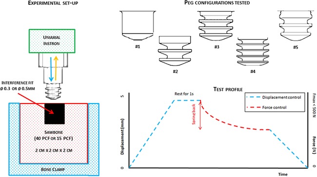
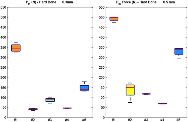
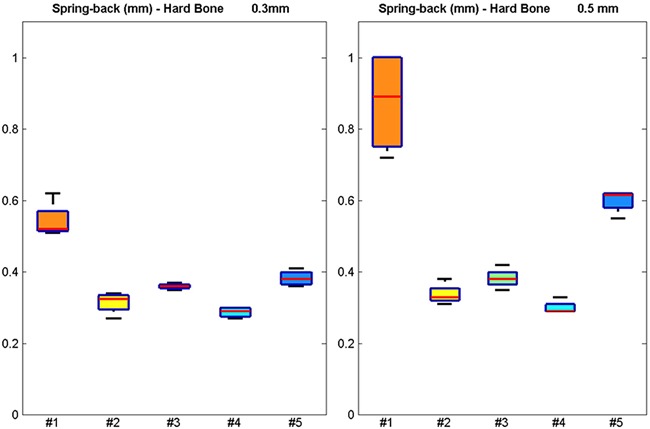
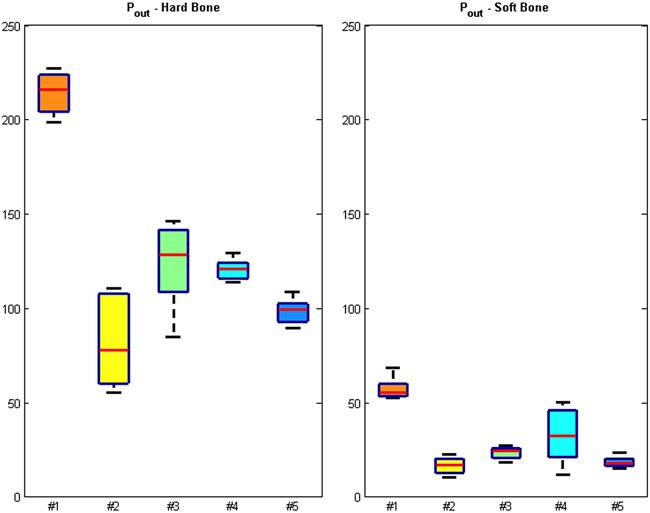
Most glenoid implants rely on large centrally located fixation features to avoid perforation of the glenoid vault in its peripheral regions. Upon revision of such components there may not be enough bone left for the reinsertion of an anatomical prosthesis. Multiple press-fit small pegs would allow for less bone resection and strong anchoring in the stiffer and denser peripheral subchondral bone. This study assessed the fixation characteristics, measured as the push-in (Pin ) and pull-out (Pout ) forces, and spring-back, measured as the elastic displacement immediately after insertion, for five different small press-fitted peg configurations manufactured out of UHMWPE cylinders (5 mm diameter and length). A total of 16 specimens for each configuration were tested in two types of solid bone substitute: Hard (40 PCF, 0.64 g/cm3 , worst-case scenario of Pin ) and soft (15 PCF, 0.24 g/cm3 , worst-case scenario of spring-back and Pout ). Two different diametric interference-fits were studied. Geometries with lower stiffness fins (large length to width aspect ratio) were the best performing designs in terms of primary fixation stability. They required the lowest force to fully seat, meaning they are less damaging to the bone during implantation, while providing the highest Pout /Pin ratio, indicating that when implanted they provide the strongest anchoring for the glenoid component. It is highlighted that drilling of chamfered holes could minimize spring-back displacements. These findings are relevant for the design of implants press-fitted pegs because primary fixation has been shown to be an important factor in achieving osseointegration and longevity of secondary fixation. © 2017 Orthopaedic Research Society. Published by Wiley Periodicals, Inc. J Orthop Res 35:2765-2772, 2017.
Keywords: cementless implant fixation; glenoid; interference fit; press-fit; shoulder.
© 2017 The Authors. Journal of Orthopaedic Research Published by Wiley Periodicals, Inc. on behalf of Orthopaedic Research Society.
Figures
Similar articles
-
Additive manufactured push-fit implant fixation with screw-strength pull out.J Orthop Res. 2018 May;36(5):1508-1518. doi: 10.1002/jor.23771. Epub 2017 Nov 22. J Orthop Res. 2018. PMID: 29023901 Free PMC article.
-
Parametric analysis of glenoid implant design and fixation type.J Orthop Res. 2017 Apr;35(4):775-784. doi: 10.1002/jor.23309. Epub 2016 Jun 20. J Orthop Res. 2017. PMID: 27219615
-
Stability of two versus three peripheral pegs of the glenoid component in modern total shoulder arthroplasty.Int Orthop. 2017 Nov;41(11):2345-2351. doi: 10.1007/s00264-017-3599-7. Epub 2017 Aug 24. Int Orthop. 2017. PMID: 28840296
-
The Humeral Implant in Shoulder Arthroplasty.J Am Acad Orthop Surg. 2017 Jun;25(6):427-438. doi: 10.5435/JAAOS-D-15-00682. J Am Acad Orthop Surg. 2017. PMID: 28459709 Review.
-
Stress shielding of the humerus in press-fit anatomic shoulder arthroplasty: review and recommendations for evaluation.J Shoulder Elbow Surg. 2018 Jun;27(6):1139-1147. doi: 10.1016/j.jse.2017.12.020. Epub 2018 Feb 5. J Shoulder Elbow Surg. 2018. PMID: 29422391 Review.
Cited by
-
Bioreactor analyses of tissue ingrowth, ongrowth and remodelling around implants: An alternative to live animal testing.Front Bioeng Biotechnol. 2023 Feb 20;11:1054391. doi: 10.3389/fbioe.2023.1054391. eCollection 2023. Front Bioeng Biotechnol. 2023. PMID: 36890911 Free PMC article.
-
Additive manufactured push-fit implant fixation with screw-strength pull out.J Orthop Res. 2018 May;36(5):1508-1518. doi: 10.1002/jor.23771. Epub 2017 Nov 22. J Orthop Res. 2018. PMID: 29023901 Free PMC article.
-
Differentiation between mechanically loose and fixed press-fit implants using quantitative acoustics and load self-referencing: A phantom study on shoulder prostheses in polyurethane foam.PLoS One. 2020 May 29;15(5):e0233548. doi: 10.1371/journal.pone.0233548. eCollection 2020. PLoS One. 2020. PMID: 32469919 Free PMC article.
-
Analysis of shoulder compressive and shear forces during functional activities of daily life.Clin Biomech (Bristol). 2018 May;54:34-41. doi: 10.1016/j.clinbiomech.2018.03.006. Epub 2018 Mar 14. Clin Biomech (Bristol). 2018. PMID: 29550641 Free PMC article.
-
The Application of Digital Volume Correlation (DVC) to Evaluate Strain Predictions Generated by Finite Element Models of the Osteoarthritic Humeral Head.Ann Biomed Eng. 2020 Dec;48(12):2859-2869. doi: 10.1007/s10439-020-02549-2. Epub 2020 Jun 22. Ann Biomed Eng. 2020. PMID: 32572730 Free PMC article.
References
-
- Franta AK, Lenters TR, Mounce D, et al. 2007. The complex characteristics of 282 unsatisfactory shoulder arthroplasties. J Shoulder Elbow Surg 16:555–562. - PubMed
-
- Churchill RS, Boorman RS, Fehringer EV, et al. 2004. Glenoid cementing may generate sufficient heat to endanger the surrounding bone. Clin Orthop Relat Res 419:76–79. - PubMed
-
- Boileau P, Avidor C, Krishnan SG, et al. 2002. Cemented polyethylene versus uncemented metal‐backed glenoid components in total shoulder arthroplasty: a prospective, double‐blind, randomized study. J Shoulder Elbow Surg 11:351–359. - PubMed
-
- Armstrong AD, Lewis GS. 2013. Design evolution of the glenoid component in total shoulder arthroplasty. JBJS Rev 1:e2–e2. - PubMed
Publication types
MeSH terms
Substances
Grants and funding
LinkOut - more resources
Full Text Sources
Other Literature Sources
