. 2017 Apr 10:8:14643.
doi: 10.1038/ncomms14643.

Light-assisted delithiation of lithium iron phosphate nanocrystals towards photo-rechargeable lithium ion batteries

Affiliations

Light-assisted delithiation of lithium iron phosphate nanocrystals towards photo-rechargeable lithium ion batteries

Andrea Paolella et al. Nat Commun. .

Abstract

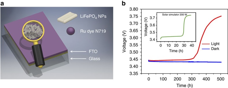
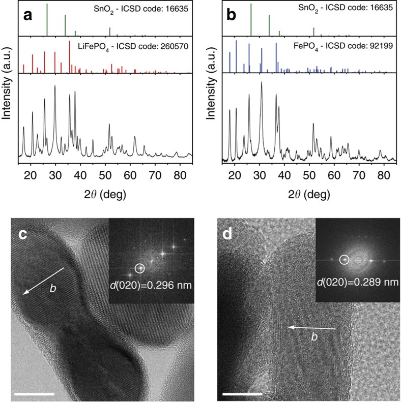
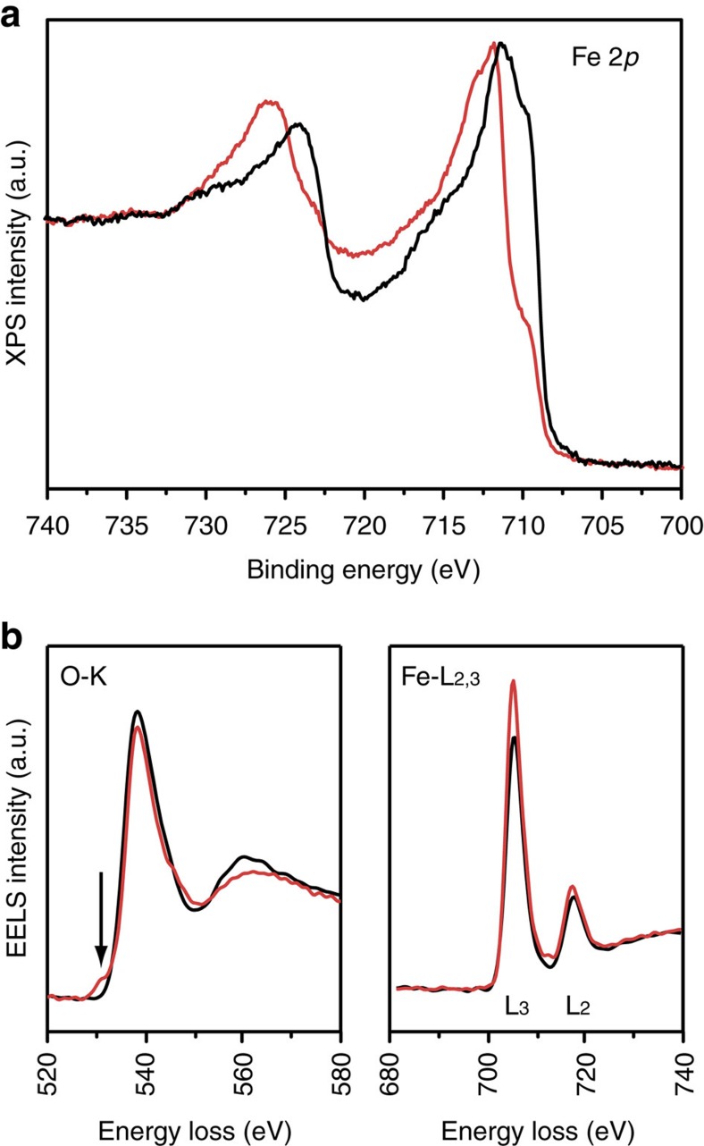
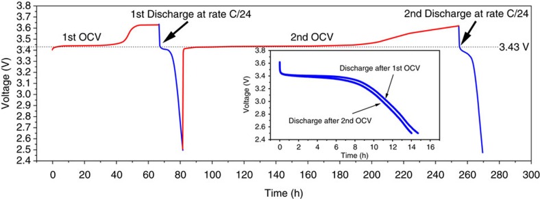
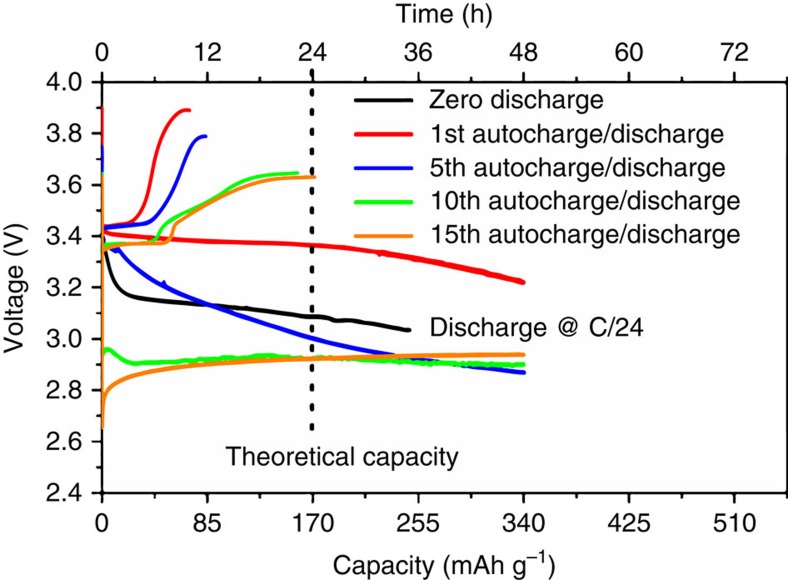
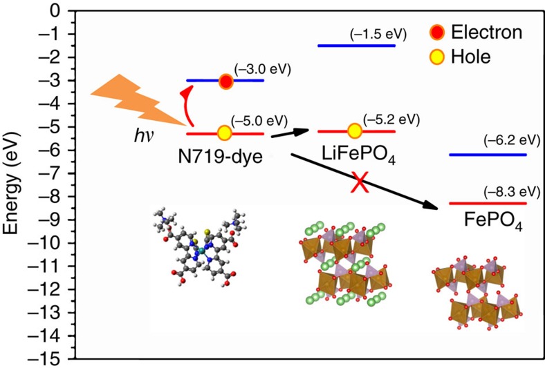
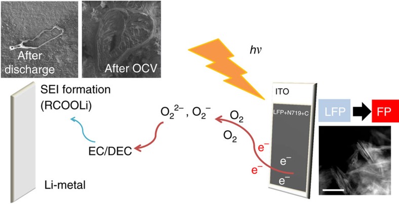
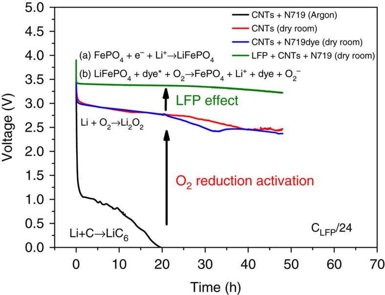
Recently, intensive efforts are dedicated to convert and store the solar energy in a single device. Herein, dye-synthesized solar cell technology is combined with lithium-ion materials to investigate light-assisted battery charging. In particular we report the direct photo-oxidation of lithium iron phosphate nanocrystals in the presence of a dye as a hybrid photo-cathode in a two-electrode system, with lithium metal as anode and lithium hexafluorophosphate in carbonate-based electrolyte; a configuration corresponding to lithium ion battery charging. Dye-sensitization generates electron-hole pairs with the holes aiding the delithiation of lithium iron phosphate at the cathode and electrons utilized in the formation of a solid electrolyte interface at the anode via oxygen reduction. Lithium iron phosphate acts effectively as a reversible redox agent for the regeneration of the dye. Our findings provide possibilities in advancing the design principles for photo-rechargeable lithium ion batteries.


Conflict of interest statement

The authors declare no competing financial interests.

Figures

Figure 1
Figure 1. LiFePO4/Dye photocathode and response to light exposure.
(a) Schematic representation of the FTO/LFP NPs/DYE electrode; (b) open circuit voltage (OCV) under Neon light exposure (red line): the voltage after a plateau at 3.40 V increased to 3.75 V and in the dark using a black box (blue line), the voltage, as expected, slightly decreases from 3.44 to 3.41 V in 500 h. The inset shows the change in OCV upon illumination with a solar simulator (green line).
Figure 2
Figure 2. Characterization of LiFePO4 nanoplatelets before and after light exposure.
(a) XRD pattern of pristine film of LFP, (b) XRD pattern of the film after light exposure, (c) HRTEM of pristine LFP (scale bars, 10 nm) and (d) HRTEM of LFP after light exposure (scale bars, 10 nm).
Figure 3
Figure 3. XPS and EELS analysis of LiFePO4 before and after light exposure.
(a) Fe 2p XPS results of the FTO–LFP–dye film before (black line) and after (red line) light exposure. The data are shown after normalization and (b) EELS spectra of oxygen K edge and iron L2,3 edge before (black) and after (red) light exposure.
Figure 4
Figure 4. Open circuit voltage and discharge curves of LiFePO4on FTO glass.
OCV charge (red lines) performed under solar simulator lighting and galvanostatic discharge (blue lines) at C/24.
Figure 5
Figure 5. Open circuit voltage and discharge curves of LiFePO4 film on ITO.
Open circuit voltage (OCV) curves and galvanostatic discharge profile of ITO@LFP+CNTs+PVDF. The 1st OCV/discharge curve is indicated with red line, the 5th one with a blue line, the 10th with green line while the 15th with orange line.
Figure 6
Figure 6. Energy band alignment of the photo-cathode components.
The arrows illustrate the desired process: the absorption of photons excites the dye, that leads to hole injection into LiFePO4 particles; the injection of holes into the charged phase of FePO4 is forbidden.The work functions of LiFePO4 and FePO4 are calculated as reported in this work; the energy band of N719 is adapted from the work of Zhang et al..
Figure 7
Figure 7. Global photo-assisted charging mechanism.
LFP photo-oxidation by holes injected by the excited dye and formation of SEI via reduction of oxygen by photoelectrons in the LFP(dye)/electrolyte/Li cell. Organic carbonate-based electrolyte is decomposed by reaction with peroxide/superoxide generated by the photogenerated electrons and oxygen. The scale bar of TEM image is 200 nm.
Figure 8
Figure 8. Discharge curves of films in different gas atmosphere at fixed C/24 discharge rate.
Discharge curves of CNTs+N719 dye film under Argon gas (black line), CNTs+ N719 dye film in dry room (blue line), film of CNTs in dry room (red line) and LiFePO4+CNTs+dye film in dry room (green line).

References

    1. Yu M. et al.. Solar-powered electrochemical energy storage: an alternative to solar fuels. J. Mater. Chem. A 4, 2766–2782 (2016).
    1. Schmidt D. et al.. Photo-rechargeable electric energy storage systems. Adv. Energy Mater. 6, 1–11 (2016).
    1. Hodes G. et al.. Photoelectrochemical energy conversion and storage using polycrystalline chalcogenide electrodes. Nature 261, 403–404 (1976).
    1. Manassen J. et al.. Photoelectrochemical energy conversion and storage. J. Electrochem. Soc. 124, 532–534 (1977).
    1. Kanbara T. et al.. Photo-rechargeable solid state battery. Solid State Ionics 40, 955–958 (1990).

Publication types