. 2017 Apr 11;7(1):790.
doi: 10.1038/s41598-017-00962-7.

Investigation of spin-orbit torque using current-induced magnetization curve

Affiliations

Investigation of spin-orbit torque using current-induced magnetization curve

Tomohiro Koyama et al. Sci Rep. .

Abstract

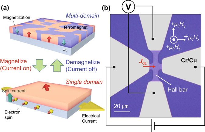
Manipulation of magnetization using current-induced torque is crucial for magnetic recording devices. Recently, the spin-orbit torque (SOT) that emerges in a ferromagnetic thin film on a heavy metal is focused as a new scheme for magnetization switching in perpendicularly magnetized systems. Since the SOT provides a perpendicular effective field to the system, the formation of a magnetic multiple domain state because of Joule heating is supressed in the magnetization reversal process. This means that high reliable switching is possible using the SOT. Here, by utilizing the SOT induced domain stability, we show that an electrical current directly injected to a perpendicularly magnetized Pt/Co/Pd system can magnetize itself, that is, current-induced magnetization process from multi to single domain state. A quantitative determination of the SOT is performed using the current-induced magnetization curve. The present results are of great importance as another approach to evaluate the SOT effect, as well as a demonstration of domain state switching caused by the SOT.


Conflict of interest statement

The authors declare that they have no competing interests.

Figures

Figure 1
Figure 1
Current-induced magnetization process and schematic of device structure. (a) When electrical current is injected into thin ferromagnet/Pt layered structure, the system is gradually magnetized and finally, single magnetic domain structure appears. (b) Device image taken by an optical microscope. A Pt/Co/Pd Hall bar structure with 5 μm width is prepared. Grey regions indicate Cr/Cu electrodes. Current source and voltage meter are connected as shown in the figure. Directions of external magnetic fields (μ 0 H x, μ 0 H y and μ 0 H z) are indicated by white arrows. The sign of electrical current is defined as positive when the current flows from left to right.
Figure 2
Figure 2
Anomalous Hall measurement under various dc currents. (a) Results of anomalous Hall resistance R Hall measurement by sweeping perpendicular field μ 0 H z. Densities of dc current J dc used here are +2.8 × 109 A/m2. Sweep rate of μ 0 H z was ~0.04 mT/s. Measurements were performed at stage temperature of 304 K. Red arrows indicate the sweep direction. (b,c) R Hall as a function of J dc obtained under μ 0 H y (b) and μ 0 H x (c) of +38 mT. Shaded area indicates the J dc region where multiple domain state appears under y-field. The error bar, which is the standard deviation of two data points, is smaller than the symbols.
Figure 3
Figure 3
Current sweep measurement under 343 K. (a) μ 0 H zR Hall curve obtained at stage temperature T d of 343 K. J dc of +2.8 × 109 A/m2 is used for the measurement. (b–d) J dc dependences of R Hall measured under (b) 0 T, (c) μ 0 H y, and (d) μ 0 H x of +38 mT, respectively. Yellow (purple) points indicate results for the positive (negative) current sweep. (e) Results of T d cooling experiment. T d is reduced from 343 K to 304 K with injecting J dc of −0.25 × 1011 (red) and −2.8 × 109 A/m2 (blue) under μ 0 H x = +38 mT. The error bar, which is the standard deviation of two data points, is smaller than the symbols.
Figure 4
Figure 4
Quantitative determination of SOT effective field. (a) Normalized R Hall as a function of μ 0 H z in range from 0 to +4.0 mT at 343 K. (b) Negative J dc dependence of normalized R Hall under μ 0 H x of +38 mT at 343 K. Zeeman energy gains by μ 0 H z and perpendicular component of the SOT effective field μ 0 H eff correspond to areas of coloured region indicated in a and b, respectively. The error bar, which is the standard deviation of two data points, is smaller than the symbols. (c) Schematic illustration displaying directions of the longitudinal effective field due to the Slonczewski-like torque μ 0 H SL and μ 0 H eff with respect to the magnetization direction m. Electrical current flows in +x direction.
Figure 5
Figure 5
Alternative domain state switching. (a) Sequence of pulsed J dc injection. J dcs of +0.4 × 1011, +2.8 × 109, and −0.4 × 1011 A/m2 are repeatedly injected into the device. The pulse duration of each J dc is 1.0 s. (b) Monitored R Hall during alternative J dc injection. Dashed lines indicate the saturation values of R Hall in single domain state.

References

    1. Brataas A, Kent AD, Ohno H. Current-induced torques in magnetic materials. Nature Mater. 2012;11:372–381. doi: 10.1038/nmat3311. - DOI - PubMed
    1. Berger L. Emission of spin waves by a magnetic multilayer traversed by a current. Phys. Rev. B. 1996;54:9353–9358. doi: 10.1103/PhysRevB.54.9353. - DOI - PubMed
    1. Slonczewski JC. Current-driven excitation of magnetic multilayers. J. Magn. Magn. Mater. 1996;159:L1–L7. doi: 10.1016/0304-8853(96)00062-5. - DOI
    1. Huai Y, Albert F, Nguyen P, Pakala M, Valet T. Observation of spin-transfer switching in deep submicron-sized and low-resistance magnetic tunnel junctions. Appl. Phys. Lett. 2004;84:3118. doi: 10.1063/1.1707228. - DOI
    1. Ikeda S, et al. A perpendicular-anisotropy CoFeB-MgO magnetic tunnel junction. Nature Mater. 2010;9:721–724. doi: 10.1038/nmat2804. - DOI - PubMed

Publication types

LinkOut - more resources