Review
. 2017 Jan;4(1):011013.
doi: 10.1117/1.JMI.4.1.011013. Epub 2017 Mar 31.

History and future technical innovation in positron emission tomography

Affiliations
Review

History and future technical innovation in positron emission tomography

Terry Jones et al. J Med Imaging (Bellingham). 2017 Jan.

Abstract

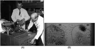
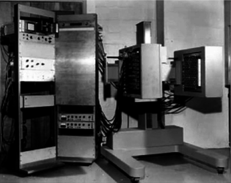
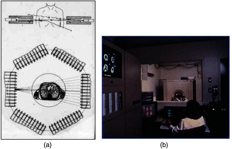
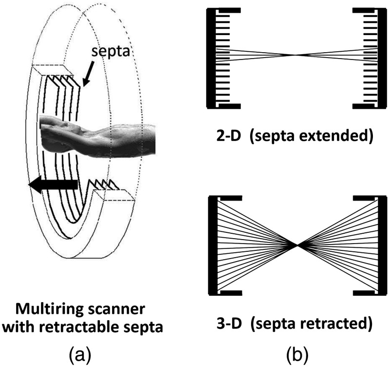
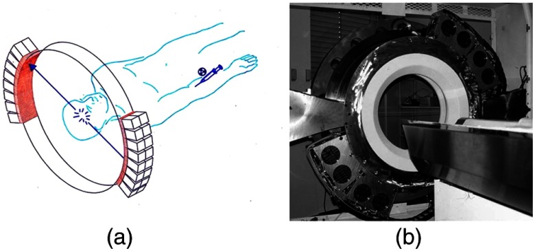
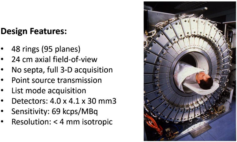
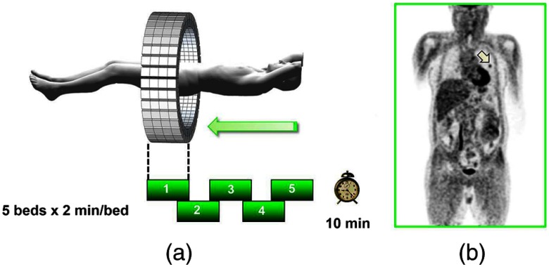
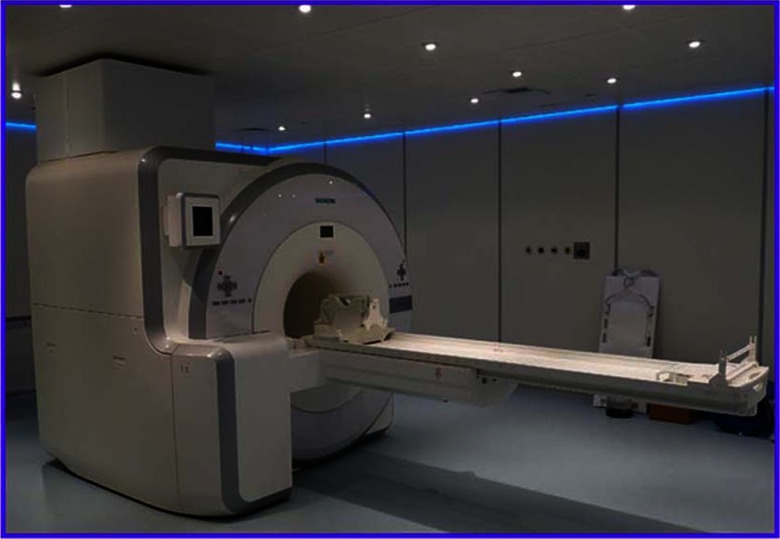
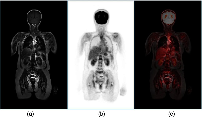
Instrumentation for positron emission tomography (PET) imaging has experienced tremendous improvements in performance over the past 60 years since it was first conceived as a medical imaging modality. Spatial resolution has improved by a factor of 10 and sensitivity by a factor of 40 from the early designs in the 1970s to the high-performance scanners of today. Multimodality configurations have emerged that combine PET with computed tomography (CT) and, more recently, with MR. Whole-body scans for clinical purposes can now be acquired in under 10 min on a state-of-the-art PET/CT. This paper will review the history of these technical developments over 40 years and summarize the important clinical research and healthcare applications that have been made possible by these technical advances. Some perspectives for the future of this technology will also be presented that promise to bring about new applications of this imaging modality in clinical research and healthcare.

Keywords: PET instrumentation; PET/CT; PET/MR; clinical applications; microPET; positron emission tomography.


Figures

Fig 1
Fig 1
(A) First clinical positron imaging device developed in 1953 by Dr. Brownell (left) and Dr. Aronow (right), and (B) the coincidence and unbalance scans of patient with recurring brain tumor. The coincidence scan (a) of a patient showing recurrence of a tumor under the previous operation site, and unbalance scan (b) showing asymmetry to the left. [Reproduced from Ref. 6].
Fig. 2
Fig. 2
One of the first positron imaging devices, the positron camera that was developed by Dr. Brownell and his team at Massachusetts Hospital (MGH) in Boston. The device became operational in 1969 and consists of two planar arrays of crystals. The patient is positioned between the two detectors.
Fig. 3
Fig. 3
(a) A schematic of the ECAT II scanner developed by EG & G ORTEC in Oak Ridge, Tennessee showing the limited solid angle coverage of the early PET scanners; the design was based on the PETT III developed in St. Louis by Ter-Pogossian and coworkers, and (b) the first commercial PET scanner, the ECAT I, shown at UCLA.
Fig. 4
Fig. 4
(a) The block detector concept invented by Casey and Nutt in 1985. The incident annihilation photon is converted to light in the scintillator and the sharing of light (b) between the four photomultiplier tubes identifies the scintillator element and localizes the incident photon. The output from the block detector is the coordinates of the element (x,y) and the energy (E) of the photon obtained by summing the light produced in the scintillator.
Fig. 5
Fig. 5
A schematic of 2-D and 3-D PET acquisition geometry. The original multiring PET scanner configuration (a) incorporated lead or tungsten shields between the detector rings thereby limiting acquisition to positron events within each ring; out-of-plane photons were eliminated by the septa. With the septa removed (b) a full 3-D acquisition is possible including both in-plane and out-of-plane photons.
Fig. 6
Fig. 6
(a) A schematic of the PRT-1, a rotating PET scanner developed at the University of Geneva, Switzerland, and CTI PET Systems, Knoxville, Tennessee; the lower-cost design comprises 40% of the detectors used in a full ring scanner and has no septa, and (b) the PRT-1 showing the two banks of opposing BGO block detectors that rotated around the patient to acquire a full, 3-D data set.
Fig. 7
Fig. 7
The high-sensitivity ECAT EXACT3D at Hammersmith Hospital, London, in 1999. At the time, this was the most sensitive PET scanner ever designed and built and it operated entirely in 3-D mode without septa.
Fig. 8
Fig. 8
A whole-body image of the patient injected with FDG is acquired by moving the bed through the scanner in discrete overlapping steps (a), typically covering the range from base of brain to thighs in 5 to 7 bed positions depending on the height of the patient. The acquired image (b) then shows the use of glucose in all organs throughout the body. A tumor would appear as a region of abnormal uptake, as shown for this patient at the apex of the lung (arrowed).
Fig. 9
Fig. 9
The improvement in image quality from modeling the system PSF for (a) the brain and (b) a whole-body scan; the image on the left is without modeling and the image on the right is with PSF modeling. Note the sharper detail and improved lesion detectability for the small lesion in the whole-body scan (arrowed).
Fig. 10
Fig. 10
The improvement in image quality due to the incorporation of TOF into the reconstruction, where (a) no TOF information and (b) with TOF information with a timing resolution of 375 ps. Images, acquired on a Philips TOF PET scanner, are courtesy of Dr Joel Karp, Philadelphia.
Fig. 11
Fig. 11
The first PET/CT scanner design (a) combining a spiral CT scanner with a rotating ART PET scanner mounted on the same support as the CT. The CT images are acquired first by moving the bed continuously through the scanner, whereas the PET images are acquired by discrete steps of the bed as shown in Fig. 7. The fused images (b) of CT and PET are displayed on the screen for reading by the attending radiologist.
Fig. 12
Fig. 12
An F18-fluorocholine PET/CT scan over the pelvic bed of a patient with prostate cancer demonstrating a choline-avid lesion in the left prostatic lobe (arrowed); (a) CT scan, (b) PET scan, (c) PET/CT fused image. Following a radical prostatectomy and histopathological analysis, this tumor was assigned a Gleason score of 4+3. Images courtesy of Dr. Joshua Schaefferkoetter, Clinical Imaging Research Centre, Singapore.
Fig. 13
Fig. 13
The combined PET/MR scanner (Siemens Healthineers) with simultaneous MR and PET imaging capability.
Fig. 14
Fig. 14
A whole-body FDG-PET/MR scan of a patient with myeloma where the FDG-PET is fused with T1-weighted MR images. Multiple vertebral lesions are seen in the coronal slice with increased uptake of FDG. The images are (a) T1-weighted MR, (b) PET, and (c) fused PET/MR. Images courtesy of Dr. Joshua Schaefferkoetter, Clinical Imaging Research Centre, Singapore.

References

    1. Jones T., “The role of positron emission tomography within the spectrum of medical imaging,” Euro. J. Nucl. Med. Mol. Imaging 23(7), 807–813 (1996).10.1007/BF00843711 - DOI - PubMed
    1. Cherry S. R., et al. , “Total-body imaging: transforming the role of positron emission tomography,” Sci. Trans. Med. 9(381) (2017).10.1126/scitranslmed.aaf6169 - DOI - PMC - PubMed
    1. Vaquero J. J., Kinahan P. E., “Positron emission tomography: current challenges and opportunities for technological advances in clinical and preclinical imaging systems,” Ann. Rev. Biomed. Eng. 17, 385–414 (2015).10.1146/annurev-bioeng-071114-040723 - DOI - PMC - PubMed
    1. Wrenn F. R., Jr., Good M. L., Handler P., “The use of positron-emitting radioisotopes for the localization of brain tumors,” Science 113(2940), 525–527 (1951).SCIEAS10.1126/science.113.2940.525 - DOI - PubMed
    1. Sweet W. H., “The uses of nuclear disintegration in the diagnosis and treatment of brain tumor,” N. Engl. J. Med. 245(23), 875–878 (1951).NEJMAG10.1056/NEJM195112062452301 - DOI - PubMed