. 2017 Apr 12:8:14982.
doi: 10.1038/ncomms14982.

Nanomechanics of individual aerographite tetrapods

Affiliations

Nanomechanics of individual aerographite tetrapods

Raimonds Meija et al. Nat Commun. .

Abstract

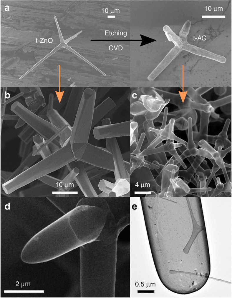
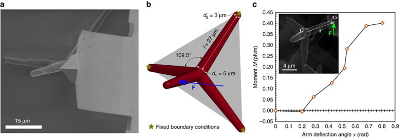
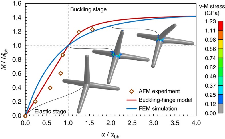
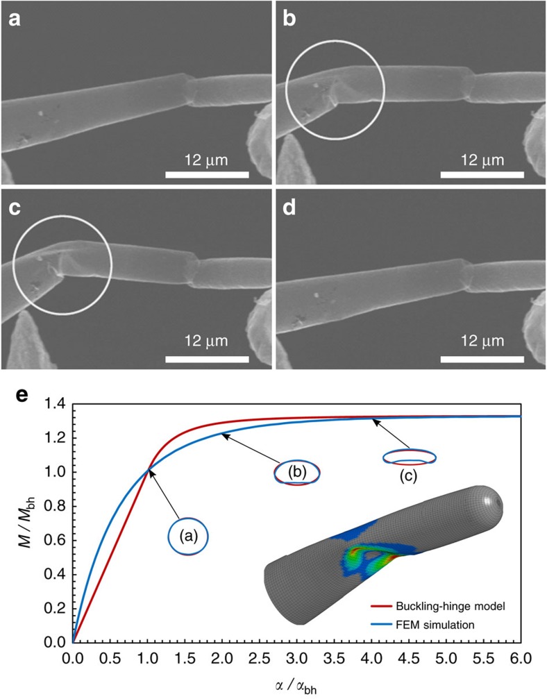
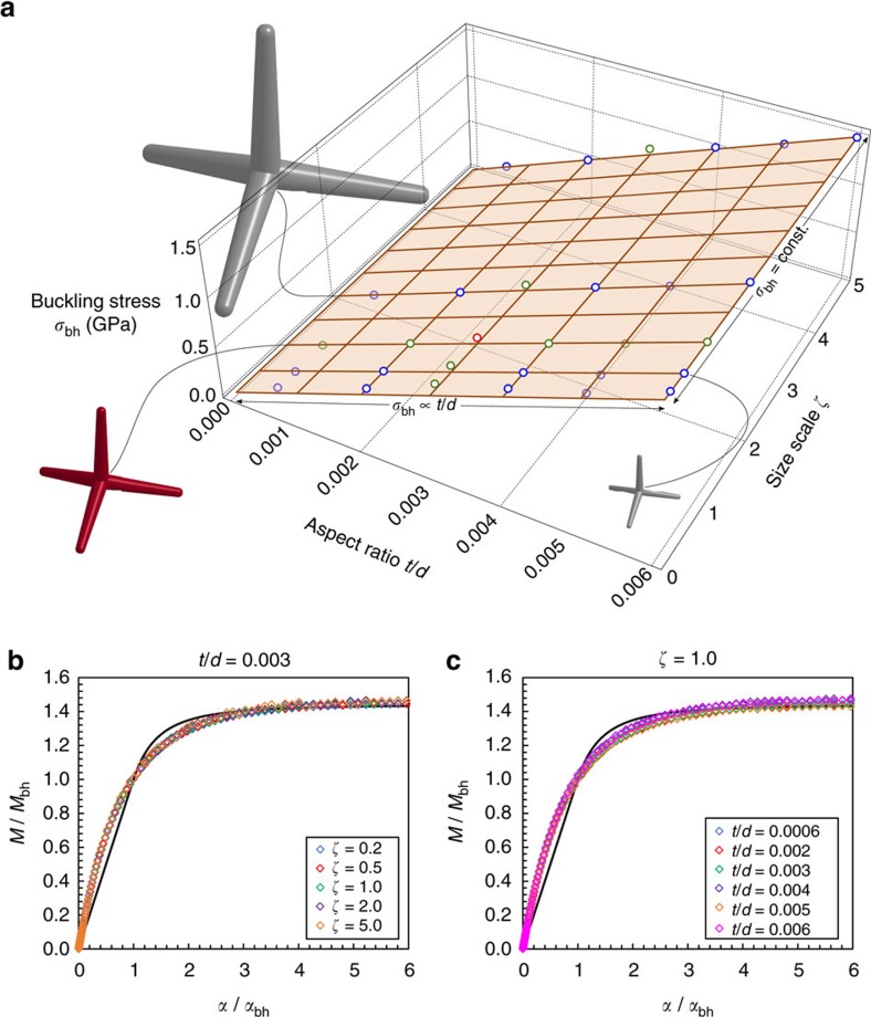
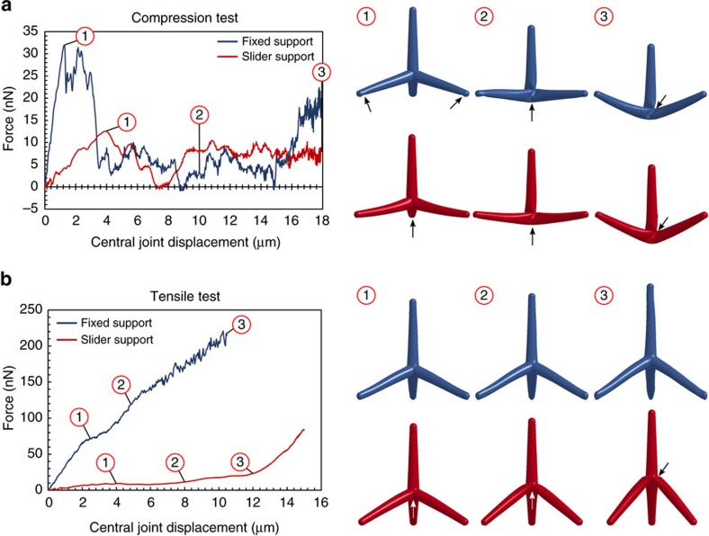
Carbon-based three-dimensional aerographite networks, built from interconnected hollow tubular tetrapods of multilayer graphene, are ultra-lightweight materials recently discovered and ideal for advanced multifunctional applications. In order to predict the bulk mechanical behaviour of networks it is very important to understand the mechanics of their individual building blocks. Here we characterize the mechanical response of single aerographite tetrapods via in situ scanning electron and atomic force microscopy measurements. To understand the acquired results, which show that the overall behaviour of the tetrapod is governed by the buckling of the central joint, a mechanical nonlinear model was developed, introducing the concept of the buckling hinge. Finite element method simulations elucidate the governing buckling phenomena. The results are then generalized for tetrapods of different size-scales and shapes. These basic findings will permit better understanding of the mechanical response of the related networks and the design of similar aerogels based on graphene and other two-dimensional materials.


Conflict of interest statement

The authors declare no competing financial interests.

Figures

Figure 1
Figure 1. Production of AG tetrapods.
(a) Schematic illustration of the formation of t-AG from sacrificial tetrapodal ZnO (t-ZnO) in the CVD process. (b,c) Typical high-resolution SEM images corresponding to t-ZnO (left) and converted t-AG networks (right), respectively. (d) Further high-resolution SEM image from the tip and middle of a t-AG arm. (e) TEM bright field image of an AG tube with closed walls.
Figure 2
Figure 2. Bending experiment on individual tetrapod attached to silica substrate.
(a) SEM image of the tested tetrapod under bending action of an AFM cantilever BL-RC-150VB from Olympus (spring constant k=2.9–50 pN nm−1). As the cantilever is moved from right to left parallel to the substrate, both the arm of the tetrapod and the cantilever are bent (see Supplementary Movie 1). (b) FEM model with detail of the geometry of the tetrapod reported in a (the tetrapod is assumed with extreme points corresponding to the vertexes of a regular tetrahedron). (c) From the AFM acquired raw data (applied force and cantilever deflection as schematically depicted in the inset picture) the current applied moment M and corresponding arm rotation angle α are determined (see Supplementary Note 1).
Figure 3
Figure 3. Normalized moment-rotation curve for bending of the tested single tetrapod.
Experimental results (dots), buckling-hinge model fitted on experimental data (red line) and FEM simulation (blue line) are reported. Contour plots of the von-Mises stress in the tetrapod outer layer of the wall is plotted (scale bar in GPa) showing the stress concentration at the central joint.
Figure 4
Figure 4. Reversible buckling of a bent AG tubular arm.
(a) Tube in the undeformed state; (b) the tube has started to buckle (position indicated by the circle); (c) tube heavily buckled with its stiffness dramatically decreased; (d) the tube recovered elastically its original shape. (e) FEM simulation derived curve (blue) and the analytical one (red) determined from the buckling-hinge model are reported. The shape of the buckling-hinge cross section at different stages from simulation and its prediction from analytical calculations are depicted. The estimated buckling-hinge parameter is γ=0.33, note that the corresponding value determined for buckling at the tetrapod central joint was γ=0.44.
Figure 5
Figure 5. Scaling of the joint mechanical properties for different tetrapod size scales (ζ=d/d0=l/l0) and tube aspect ratios (t/d).
(a) Maximum buckling stress σbh=Eɛbh at the joint section from numerical simulations (dots) compared with the best-fit surface of equation (2). It emerges nearly independence of the buckling stress/strain from the size scale (t/d=const.) and linear dependence with respect to the aspect ratio t/d. The red dot represents the nominal tested tetrapod of Fig. 3 (ζ=1, t/d=0.003) while the green dots correspond to its size scaling with t/d=const.=0.003, or to the aspect ratio scaling only (ζ=1). Tetrapod at three different size scales (ζ=0.2, 1.0, 2.0) are depicted. (b) Dimensionless moment-rotation curves of the 5 performed simulations with t/d=const.=0.003 compared to the analytical prediction of the buckling-hinge model (continuous line). (c) Dimensionless moment-rotation curves of the 6 performed simulations with ζ=1 compared to the analytical prediction of the buckling-hinge model (continuous line).
Figure 6
Figure 6. Force–displacement curves of a single tetrapod under compression or tension and fixed or sliding boundary conditions as computed by FEM simulations.
The boundary configuration in the FEM images is identified by the tetrapod colour according to the graph legend. The locations of the buckling-hinge formations are highlighted with the arrows. (a) Compression tests showing a typical snap-through-like global instability under displacement control. The reactive moments at the clamps yield there to the formation of buckling-hinges which disappear for large displacement leading to the formation of a central hinge . The sliding boundary conditions led the formation of the hinge only at the central joint where the maximum moment takes place. (b) Tension test showing how the fixed boundary conditions do not allow the formation of a buckling hinge thus, the tetrapod behaviour is governed by arm bending. In the sliding boundary conditions case, stiffening after displacement level is due to the base arms alignment along the loading direction after the formation of the central hinge. See Supplementary Movies 6–9 of the 4 tests.

References

    1. Liu F., Piao Y., Choi J. S. & Seo T. S. Three-dimensional graphene micropillar based electrochemical sensor for phenol detection. Biosens. Bioelectron. 50, 387–392 (2013). - PubMed
    1. Li W. et al.. High-density three-dimension graphene macroscopic objects for high-capacity removal of heavy metal ions. Sci. Rep. 3, 2125 (2013). - PMC - PubMed
    1. Wang H., Sun K., Tao F., Stacchiola D. J. & Hu Y. H. 3D honeycomb like structured graphene and its high efficiency as a counter electrode catalyst for dye sensitized solar cells. Angew. Chem. Int. Ed. 125, 9380–9384 (2013). - PubMed
    1. Chen S. et al.. Elastic carbon foam via direct carbonization of polymer foam for flexible electrode and organic chemical adsorption. Energy Environ. Sci. 6, 2435–2439 (2013).
    1. Choi B. G., Yang M., Hong W. H., Choi J. W. & Huh Y. S. 3D macroporous graphene frameworks for supercapacitors with high energy and power densities. ACS Nano 6, 4020–4028 (2012). - PubMed

Publication types

LinkOut - more resources