Review
. 2017 Apr 13;13(5):455-463.
doi: 10.1038/nchembio.2353.

The chemical basis for electrical signaling

Affiliations
Review

The chemical basis for electrical signaling

William A Catterall et al. Nat Chem Biol. .

Abstract

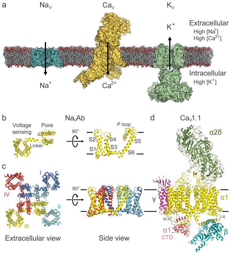
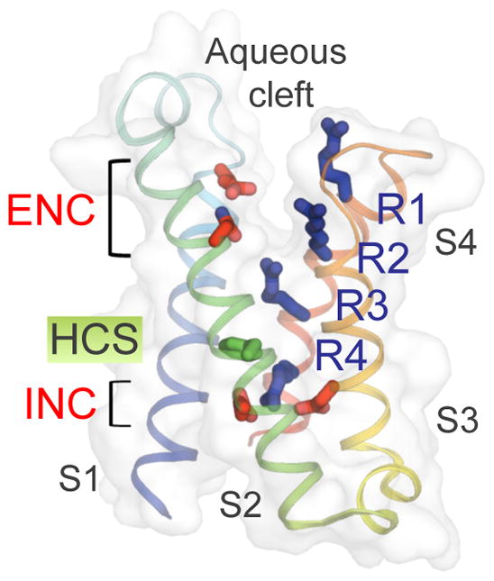
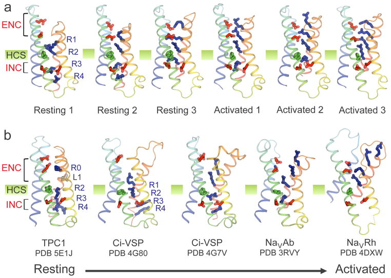
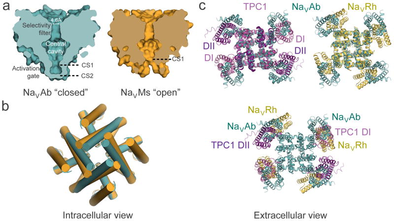
Electrical signals generated by minute currents of ions moving across cell membranes are central to all rapid processes in biology. Initiation and propagation of electrical signals requires voltage-gated sodium (NaV) and calcium (CaV) channels. These channels contain a tetramer of membrane-bound subunits or domains comprising a voltage sensor and a pore module. Voltage-dependent activation occurs as membrane depolarization drives outward movements of positive gating changes in the voltage sensor via a sliding-helix mechanism, which leads to a conformational change in the pore module that opens its intracellular activation gate. A unique negatively charged site in the selectivity filter conducts hydrated Na+ or Ca2+ rapidly and selectively. Ion conductance is terminated by voltage-dependent inactivation, which causes asymmetric pore collapse. This Review focuses on recent advances in structure and function of NaV and CaV channels that expand our current understanding of the chemical basis for electrical signaling mechanisms conserved from bacteria to humans.


Figures

Figure 1
Figure 1. Overall architecture of voltage-gated sodium, calcium, and potassium channels
a, Model of representative NaV, CaV, and KV channels in a lipid membrane. From left to right: bacterial NaVAb (cyan), mammalian CaV1.1 complex with auxiliary subunits (yellow), and mammalian KV1.2/2.1 chimera complex with cytoplasmic β subunits (green). b, Structure of the bacterial sodium channel NaVAb single subunit. The structure comprises the voltage-sensing module (S1–S4) connected to the pore module (S5–S6) via the S4–S5 linker. The P loop connects the S5 and S6 segments and contains the ion selectivity filter motif (Fig. 5). c, NaVAb homotetramer with domain swapping illustrated by different color for each subunit. The pore is located at the center of the tetramer with the voltage-sensing module interacting with the pore module of the neighboring subunit. d, Single particle cryo-EM reconstruction of CaV1.1 with NaVAb-like core α1 subunit highlighted in yellow and the α1 C-terminal domain in pink. Auxiliary α2δ, β, and γ subunits are colored in green, cyan, and magenta, respectively. Black lines depict membrane boundaries. The C-terminal domain of CaV1 channels is exceptionally large, and only partially resolved in the cryo-EM structure (Fig. 1d). The structure reveals an unexpected interaction between the intracellular domain III–IV linker and the intracellular C-terminal domain of the α1 subunit. The domain III–IV linker serves as the fast-inactivation gate in eukaryotic sodium channels (see below), and structure-function studies suggest that it also interacts with the C-terminal domain,. The functional significance of this conserved interaction in CaV1 channels is unknown.
Figure 2
Figure 2. Structure of the voltage-sensing module of NavAb
The TM helices are colored from S1 to S4 segments in blue to red spectrum. Side chains of the extracellular and intracellular negative charge cluster (ENC and INC) amino acids are highlighted in red and side chains of the positive gating charge Arg residues (R1–R4) in blue. The hydrophobic constriction site (HCS) is shown in green. The aqueous cleft can be seen between the S1–S2 and S3–S4 hairpins from the overlaying semi-transparent surface.
Figure 3
Figure 3. Structural models of resting and activated states of voltage-sensing modules
a, Structural models of voltage-sensing module of NaChBac from Rosetta Membrane computational modeling. The Arg gating charges on S4 moves outward from the most resting state (Resting 1) to the most activated state (Activated 3) via several intermediates, passing through the HCS and exchanging their interactions with different INC and ENC side chains. b, Structures of voltage-sensing modules from available X-ray crystallographic structures of voltage-sensitive ion channels and enzyme. From left to right: domain 2 (resting state) of plant TPC1; resting state of Ci-VSP; activated state of Ci-VSP; activated state of NaVAb; inactivated state of NaVRh. Same color scheme as Fig. 2 is used.
Figure 4
Figure 4. Structural model of conformational changes during channel activation and pore opening
a, Pore-opening conformational change between the closed pore of NaVAb and the open pore of NaVMs. NaVAb structure (left, cyan) contains two pore constriction sites (CS1 and CS2) with CS2 site completely sealing the pore. NaVMs structure (right, orange) contains one pore constriction site (CS1) that remains open to allow hydrated sodium ion to pass through. b, Superposition of NaVAb and NaVMs pores viewed from the intracellular side. A counterclockwise twisting motion of the S6 segment from the closed pore of NaVAb to the open pore of NaVMs shifts the end of S6 helix outward to dilate the pore diameter. c, Channel activation involves clockwise rotation of the voltage sensor around the pore. Top left: Superposition of TPC1 (light purple for activated state domain I (DI) and dark purple for resting state domain II (DII)) and NaVAb (cyan) structures. Top right: Superposition of NaVRh (yellow) and NaVAb (cyan) structures. Bottom: Overlay of voltage-sensing modules in TPC1, NaVAb, and NaVRh as in the top panel but with the pore modules of TPC1 and NaVRh omitted for clarity. The voltage-sensing module progressively rotates around the pore from the most resting state in TPC1 DII to increasingly activated states in NaVAb, TPC1 DI, and NaVRh.
Figure 5
Figure 5. Chemical mechanism of ion permeation and selectivity of NaV and CaV channels with structural models of their ion selectivity filters with ions bound
a, Na+ selectivity filter (TLESWSM) in NaVAb. b, Representative conformations of Na+ selectivity filter from molecular dynamic simulations of sodium permeation in NaVAb. Conformational dunking of Glu side chain of the high-field strength site allows direct coordination of Na+ ions. c, Ca2+ selectivity filter (TLDDWSN) in CaVAb. d, Hydrated Ca2+ bound in the CaVAb selectivity filter. e, Ca2+ selectivity filter of CaV1.1 from Domains I (TMEGWTD) and III (TFEGWPQ). f, Ca2+ selectivity filter of CaV1.1 from Domains II (TGEDWNS) and IV (TGEAWQE). Na+ (purple) and Ca2+ (green) ions are shown with semi-transparent ionic sphere. Dash lines indicate network of interactions among coordinated water molecules with the ions and protein atoms from high-filed strength site (Glu in NaVAb and CaV1.1, and Asp in CaVAb, underlined) and backbone carbonyls of Leu and Thr. For clarity, only two opposing subunits in the tetramer are shown. Of note, a distantly related non-voltage-gated Ca2+ channel has a different architecture of its outer pore with Asp residues from each subunit directly binding dehydrated Ca2+ in a closed state structure. The significance of this binding mode in ion conductance is unknown.
Figure 6
Figure 6. Conformational changes in the pore associated with slow inactivation
a, An extracellular view of the pore through the selectivity filter. The selectivity filter collapses from a four-fold symmetric shape in pre-open NaVAb (left) to an oval shape in inactivated NaVAb (middle) to a completely closed pore in inactivated NaVRh (right). b, An intracellular view of the pore at the C-termini of the S6 segments. The pore distorts from a square shape in the pre-open NaVAb structure to a parallelogram shape in the inactivated NaVAb and NaVRh structures.

References

    1. Hille B. Ionic Channels of Excitable Membranes. 3. Sinauer Associates Inc; 2001.
    1. Jan LY, Jan YN. Voltage-gated potassium channels and the diversity of electrical signalling. J Physiol. 2012;590:2591–2599. - PMC - PubMed
    1. Long SB, Campbell EB, Mackinnon R. Crystal structure of a mammalian voltage-dependent Shaker family K+ channel. Science. 2005;309:897–903. - PubMed
    1. Tao X, Lee A, Limapichat W, Dougherty DA, MacKinnon R. A gating charge transfer center in voltage sensors. Science. 2010;328:67–73. - PMC - PubMed
    1. Vargas E, et al. An emerging consensus on voltage-dependent gating from computational modeling and molecular dynamics simulations. J Gen Physiol. 2012;140:587–594. - PMC - PubMed

References*

    1. Prindle A, et al. Ion channels enable electrical communication in bacterial communities. Nature. 2015;527:59–63. - PMC - PubMed
    1. Eckert R, Brehm P. Ionic mechanisms of excitation in Paramecium. Annu Rev Biophys Bioeng. 1979;8:353–383. - PubMed
    1. Hille B. Ionic Channels of Excitable Membranes. 3. Sinauer Associates Inc; 2001.
    1. Hodgkin AL, Huxley AF. A quantitative description of membrane current and its application to conduction and excitation in nerve. J Physiol. 1952;117:500–544. - PMC - PubMed
    1. Catterall WA. The molecular basis of neuronal excitability. Science. 1984;223:653–661. - PubMed

Publication types