. 2017 Oct;64(10):2439-2449.
doi: 10.1109/TBME.2017.2691720. Epub 2017 Apr 7.

Position and Orientation Insensitive Wireless Power Transmission for EnerCage-Homecage System

Position and Orientation Insensitive Wireless Power Transmission for EnerCage-Homecage System

Yaoyao Jia et al. IEEE Trans Biomed Eng. 2017 Oct.

Abstract

We have developed a new headstage architecture as part of a smart experimental arena, known as the EnerCage-HC2 system, which automatically delivers stimulation and collects behavioral data over extended periods with minimal small animal subject handling or personnel intervention in a standard rodent homecage. Equipped with a four-coil inductive link, the EnerCage-HC2 system wirelessly powers the receiver (Rx) headstage, irrespective of the subject's location or head orientation, eliminating the need for tethering or carrying bulky batteries. On the transmitter (Tx) side, a driver coil, five high-quality (Q) factor segmented resonators at different heights and orientations, and a closed-loop Tx power controller create a homogeneous electromagnetic (EM) field within the homecage 3-D space, and compensate for drops in power transfer efficiency (PTE) due to Rx misalignments. The headstage is equipped with four small slanted resonators, each covering a range of head orientations with respect to the Tx resonators, which direct the EM field toward the load coil at the bottom of the headstage. Moreover, data links based on Wi-Fi, UART, and Bluetooth low energy are utilized to enables remote communication and control of the Rx. The PTE varies within 23.6%-33.3% and 6.7%-10.1% at headstage heights of 8 and 20 cm, respectively, while continuously delivering >40 mW to the Rx electronics even at 90° rotation. As a proof of EnerCage-HC2 functionality in vivo, a previously documented on-demand electrical stimulation of the globus pallidus, eliciting consistent head rotation, is demonstrated in three freely behaving rats.


Figures

Fig. 1
Fig. 1
(a) Definition of normal height and orientation of the headstage when the rat is walking. (b) Problem of Tx-Rx increased distance when the animal rear on its hind limbs. (c) Angular misalignment of the headstage attached in a freely behaving animal when the head is turned downward.
Fig. 2
Fig. 2
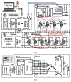
A simplified conceptual representation of the proposed EnerCage-HC2 system for closed-loop wireless powering and communication with a headstage attached to or implanted in a small freely behaving animal.
Fig. 3
Fig. 3
Schematic diagram of (a) the key circuits involved in the wireless power transmission from the Tx side to the Rx side and (b) the stimulator circuit implemented on two PCBs in the headstage (see Fig. 8b).
Fig. 4
Fig. 4
Simplified flowchart of the data communication algorithm in EnerCage-HC2 system, as implemented in the algorithm among CC2541 MCU, CC2540 MCU, and Raspberry Pi (RPi).
Fig. 5
Fig. 5
3D view of the 4-coil inductive link, including L1 and L21–L25 under and around the homecage, respectively, on the Tx side, and L31–L34 and L4 around and inside the headstage, respectively, on the Rx side.
Fig. 6
Fig. 6
Poynting vector simulations in HFSS, showing top view of L25 as a complete loop, with two segments, and with four segments, when the headstage is located at the center, 20 cm from the bottom of the homecage.
Fig. 7
Fig. 7
SAR simulation in HFSS, presenting the maximum of the average SAR values for the tissue layers with the proposed 4-coil inductive link.
Fig. 8
Fig. 8
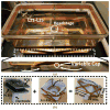
(a) The EnerCage-HC2 proof-of-concept prototype with L1 and its driver located at the bottom of the homecage, and copper foil resonators with a single variable capacitor. (b) A close up view of the headstage and its internal/external components.
Fig. 9
Fig. 9
PTE measurement setup using a VNA when RL > 50 Ω.
Fig. 10
Fig. 10
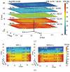
(a) Measured PTE of the 4-coil inductive link when the headstage is swept inside the homecage across XY plane at the heights of 4 cm, 8 cm, 12 cm, 16 cm, and 20 cm. (b) Measured PTE when the headstage is swept across the XZ plane (Y = 0 cm), at a height of 8 cm a) with and b) without L25.
Fig. 11
Fig. 11
Measured PTE of the proposed 4-coil inductive link when the headstage is swept across XY plane in the cage, at H = 8 cm, and rotated by (a) 30°, (b) 60°, and (c) 90° along X axis.
Fig. 12
Fig. 12
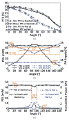
Headstage measurements in the middle of the homecage at H = 8 cm: (a) Comparison between PTE vs. rotation with proposed slanted L3s and flat L3 in [35]. (b) Comparison between PDL and PA supply voltage vs. rotation with and without CLPC. (c) Comparison between PDL and Tx power vs. rotation with proposed slanted L3s and flat L3 in [29] in CLPC.
Fig. 13
Fig. 13
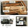
(a) In vivo experimental setup for 1-ch DBS in a freely behaving rat. (b) Close up view of the controller block including a custom-designed cape. (c) GUI running on a PC, including a live video stream from a MS-Kinect® for behavioral monitoring of the animal subject [38].
Fig. 14
Fig. 14
Electrode placement and Histology. (a) The red dots represent placement of the tip of the electrodes, all in the GPi. (b) Sample brain slice, stained with Nissl staining. The dark track in the center of the picture is the trace of the electrode insertion in the brain.
Fig. 15
Fig. 15
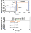
(a) Stimulation pulses in trial # 1 and # 2 of rat #3, acquired by decoding the data transmitted from the headstage via BLE while the animal was freely moving in the homecage. (b) Time-aligned stimulation pulses in trial #1.
Fig. 16
Fig. 16
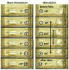
Comparing head turning behavior within 10 s between the actual and sham stimulations in rat 3. The relative time before, during, and after stimulation is indicated in seconds in the blue circle in each frame with the measured head turning angle next to it.
Fig. 17
Fig. 17
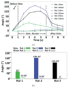
(a) Head rotation angle vs. time during actual stimulation in comparison with 9 s at the end of the 1st minute of a trial as control. (b) The mean maximum head rotations of each rat during actual and sham stimulations.
Fig. 18
Fig. 18
Voltage doubler output (VDD) and PA supply voltage (VPA) variations during a 5 s stimulation episode in trial #1 and #2, showing the VDD staying within a user-defined window, thanks to CLPC, despite head rotation and load variation during stimulation.

Similar articles

Cited by

References

    1. Grill WM, Norman SE, Bellamkonda RV. Implanted neural interfaces: biochallenges and engineered solutions. Annual review of biomedical engineering. 2009 Aug;11:1–24. - PubMed
    1. Donoghue JP. Bridging the brain to the world: a perspective on neural interface systems. Neuron. 2008 Nov;60:511–521. - PubMed
    1. Aravanis AM, et al. An optical neural interface: in vivo control of rodent motor cortex with integrated fiberoptic and optogenetic technology. Journal of neural engineering. 2007 Jun;4:S143. - PubMed
    1. Shaw FZ, Lai CJ, Chiu TH. A low-noise flexible integrated system for recording and analysis of multiple electrical signals during sleep–wake states in rats. Journal of neuroscience methods. 2002 Jul;118:77–87. - PubMed
    1. Rossi MA, Go V, Murphy T, Fu Q, Morizio J, Yin HH. A wirelessly controlled implantable LED system for deep brain optogenetic stimulation. Frontiers in Integrative Neuroscience. 2015 Feb;9:8. - PMC - PubMed

Publication types