

Zygomaticomaxillary suture maturation: A predictor of maxillary protraction? Part I - A classification method
- PMID: 28414869
- PMCID: PMC5503123
- DOI: 10.1111/ocr.12143
Zygomaticomaxillary suture maturation: A predictor of maxillary protraction? Part I - A classification method
Abstract
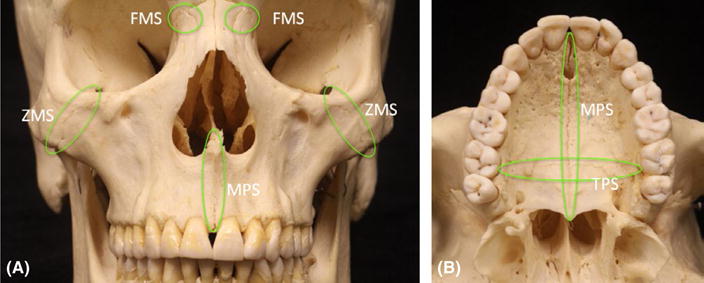
Objective: The aim of this study was to present a method of classifying the maturational level of the zygomaticomaxillary sutures (ZMSs).
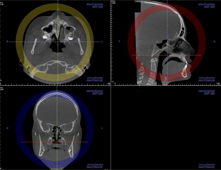
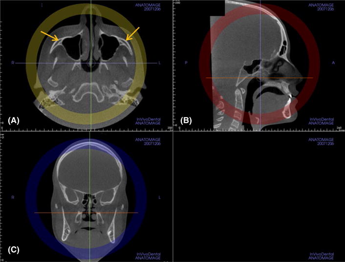
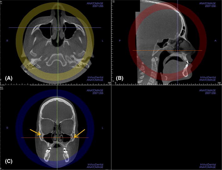
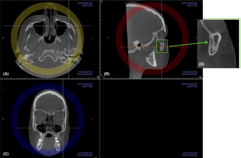
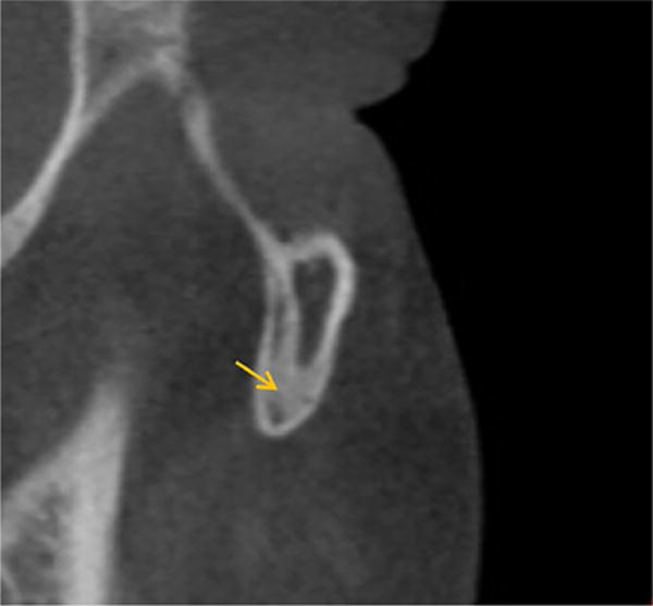
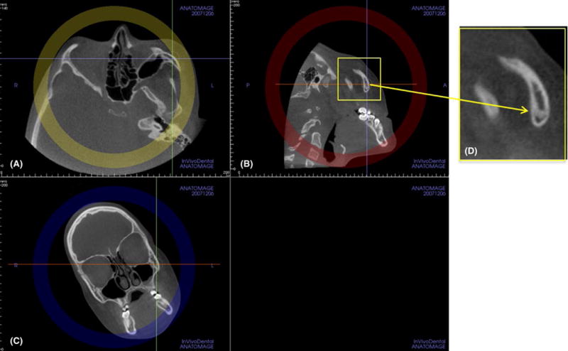
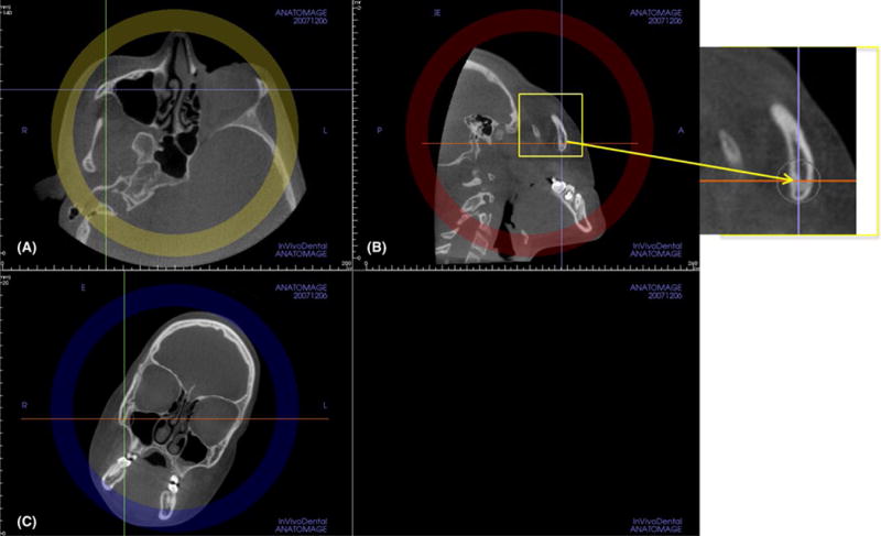
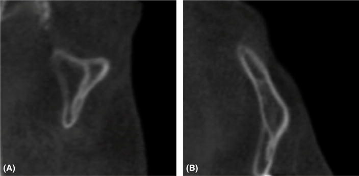
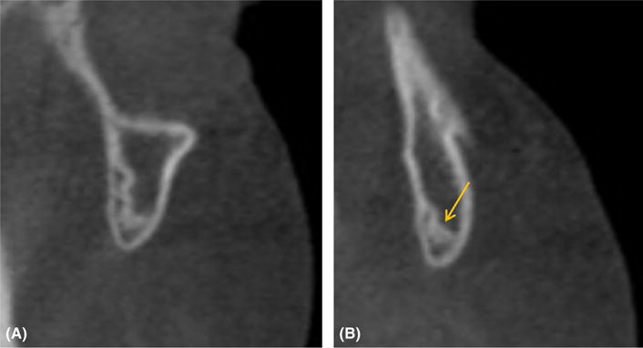
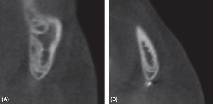
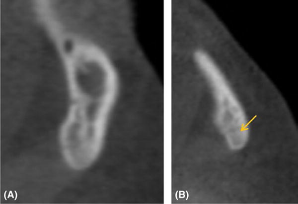
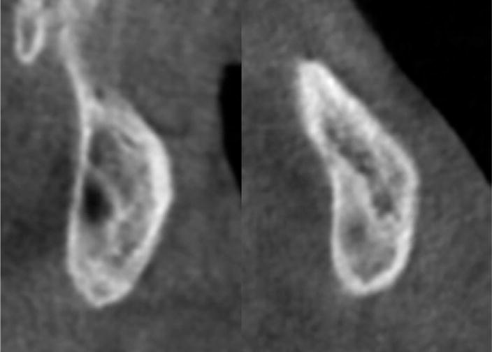
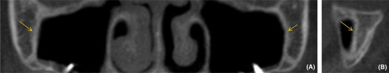
Methods: Cone-beam CT (CBCT) images from 74 subjects (5.6-58.4 years) were examined to define the radiographic stages of ZMS maturation. Five stages of maturation of the ZMS were identified and defined: Stage A-uniform high-density sutural line, with no or little interdigitation; Stage B-scalloped appearance of the high-density sutural line; Stage C-two parallel, scalloped, high-density lines, separated in some areas by small low-density spaces; Stage D-fusion in the inferior portion of the suture; and Stage E-complete fusion. Intra- and inter-examiner agreements were evaluated by weighted kappa tests.
Results: The intra- and inter-examiners reproducibility values demonstrated substantial to almost perfect agreement. No fusion of ZMSs was observed in patients up to 10 years of age. From 10 to 15 years, all maturational stages were identified. After 15 years of age, the majority of patients showed fusion of ZMSs.
Conclusions: The classification of ZMS maturation using CBCT is a reliable method that allows the assessment of the morphology of the ZMSs in the individual patient.
Keywords: cone-beam computed tomography; cranial sutures; growth and development.
© 2017 John Wiley & Sons A/S. Published by John Wiley & Sons Ltd.
Figures
Similar articles
-
Zygomaticomaxillary suture maturation: Part II-The influence of sutural maturation on the response to maxillary protraction.Orthod Craniofac Res. 2017 Aug;20(3):152-163. doi: 10.1111/ocr.12191. Epub 2017 Jun 29. Orthod Craniofac Res. 2017. PMID: 28660731 Free PMC article.
-
Midpalatal suture maturation: classification method for individual assessment before rapid maxillary expansion.Am J Orthod Dentofacial Orthop. 2013 Nov;144(5):759-69. doi: 10.1016/j.ajodo.2013.04.022. Am J Orthod Dentofacial Orthop. 2013. PMID: 24182592 Free PMC article.
-
Cone beam computed tomography evaluation of midpalatal suture maturation in adults.Int J Oral Maxillofac Surg. 2017 Dec;46(12):1557-1561. doi: 10.1016/j.ijom.2017.06.021. Epub 2017 Jul 14. Int J Oral Maxillofac Surg. 2017. PMID: 28716474
-
Cone Beam Computed Tomography evaluation of midpalatal suture maturation according to age and sex: A systematic review.Eur J Paediatr Dent. 2022 Mar;23(1):44-50. doi: 10.23804/ejpd.2022.23.01.08. Eur J Paediatr Dent. 2022. PMID: 35274542
-
Sutural biology and the correlates of craniosynostosis.Am J Med Genet. 1993 Oct 1;47(5):581-616. doi: 10.1002/ajmg.1320470507. Am J Med Genet. 1993. PMID: 8266985 Review.
Cited by
-
Clinical Management of Facemasks for Early Treatment of Class III Malocclusion: A Survey among SIDO Members.Dent J (Basel). 2024 Jul 5;12(7):207. doi: 10.3390/dj12070207. Dent J (Basel). 2024. PMID: 39056994 Free PMC article.
-
Maxillofacial morphological factors related to acceleration of maxillary growth attributed to facial mask treatment: a structural superimposition study.Prog Orthod. 2019 Jan 14;20(1):2. doi: 10.1186/s40510-018-0254-9. Prog Orthod. 2019. PMID: 30637515 Free PMC article.
-
Bone-anchored maxillary protraction (BAMP): A review.J Orthod Sci. 2022 May 4;11:8. doi: 10.4103/jos.jos_153_21. eCollection 2022. J Orthod Sci. 2022. PMID: 35754417 Free PMC article. Review.
-
Skeletal Changes in Growing Cleft Patients with Class III Malocclusion Treated with Bone Anchored Maxillary Protraction-A 3.5-Year Follow-Up.J Clin Med. 2021 Feb 13;10(4):750. doi: 10.3390/jcm10040750. J Clin Med. 2021. PMID: 33668503 Free PMC article.
-
Reliability assessment of craniofacial and airway measurements: a comparative study between multidetector computed tomography and cone-beam computed tomography.Angle Orthod. 2025 Jan 1;95(1):57-77. doi: 10.2319/022124-131.1. Angle Orthod. 2025. PMID: 39317376 Free PMC article.
References
-
- Melsen B, Melsen F. The postnatal development of the palatomaxillary region studied on human autopsy material. Am J Orthod. 1982;82:329–342. - PubMed
-
- Kambara T. Dentofacial changes produced by extraoral forward force in the Macaca irus. Am J Orthod. 1977;71:249–277. - PubMed
-
- Jackson G, Kokich V, Shapiro P. Experimental and post-experimental response to anteriorly directed extraoral force in young Macaca nemestrina. Am J Orthod. 1979;75:318–333. - PubMed
-
- Nanda R, Hickory W. Zygomaticomaxillary suture adaptations incident to anteriorly-directed forces in rhesus monkeys. Angle Orthod. 1984;54:199–210. - PubMed
-
- Zhao N, Xu Y, Chen Y, Xu Y, Han X, Wang L. Effects of class III magnetic orthopedic forces on the craniofacial sutures of rhesus monkeys. Am J Orthod Dentofacial Orthop. 2008;133:401–409. - PubMed
MeSH terms
Grants and funding
LinkOut - more resources
Full Text Sources
Other Literature Sources
