. 2017 May;18(3):118-129.
doi: 10.1002/acm2.12082. Epub 2017 Apr 19.

MLC-based penumbra softener of EDW borders to reduce junction inhomogeneities

Affiliations

MLC-based penumbra softener of EDW borders to reduce junction inhomogeneities

Stanislaw Szpala et al. J Appl Clin Med Phys. 2017 May.

Abstract

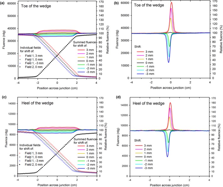
Junctions of fields are known to be susceptible to developing cold or hot spots in the presence of even small geometrical misalignments. Reduction of these dose inhomogeneities can be accomplished through decreasing the dose gradients in the penumbra, but currently it cannot be done for enhanced dynamic wedges (EDW). An MLC-based penumbra softener was developed in the developer mode of TrueBeam linacs to reduce dose gradients across the side border of EDWs. The movement of each leaf was individually synchronized with the movement of the dynamic Y jaw to soften the penumbra in the same manner along the entire field border, in spite of the presence of the dose gradient of the EDW. Junction homogeneity upon field misalignment for side-matched EDWs was examined with the MV imager. The fluence inhomogeneities were reduced from about 30% per mm of shift of the field borders for the conventional EDW to about 2% per mm for the softened-penumbra plan. The junction in a four-field monoisocentric breast plan delivered to the Rando phantom was assessed with film. The dose inhomogeneities across the junction in the superior-inferior direction were reduced from about 20% to 25% per mm for the conventional fields to about 5% per mm. The dose near the softened junction of the breast plan with no shifts did not deviate from the conventional plan by more than about 4%. The newly-developed softened-penumbra junction of EDW (and/or open) fields was shown to reduce sensitivity to misalignments without increasing complexity of the planning or delivery. This methodology needs to be adopted by the manufacturers for clinical use.

Keywords: dose homogeneity; enhanced dynamic wedge; feathered junction; penumbra modifier.


Figures

Figure 1
Figure 1
A fluence dip (or a spike; not shown) across the junction of two slightly misaligned fields can be reduced through softening the penumbra of the individual fields. (a) An ideal junction of fields with 2 cm penumbra. (b) The same junction after moving field 2 away from the junction by 1 cm. (c) An ideal junction for fields with 4 cm penumbra. (d) The junction for fields with 4 cm penumbra after the same shift of field 2 as in (b), i.e., 1 cm.
Figure 2
Figure 2
The BEV and the junction profiles of side‐matched EDWs with penumbra widening employing dynamic movement of the X jaw. (a) The BEV showing location of the dynamic Y jaw at the beginning (B), middle (M) and ending (E) of its movement together with the corresponding locations of the X jaw (dotted lines, color coded to match the locations of the dynamic Y jaw), such that a uniform junction (shown in (b)) is formed at y = ‘E’, but a non‐uniform one (shown in (c)) at y = ‘M’. (d): The BEV showing movement of the X jaw synchronized with the dynamic Y jaw such that the profile (shown in (f)) at y = ‘M’ is flat, but is non‐uniform at y = ‘E’ (shown in (e)).
Figure 3
Figure 3
A snapshot of the BEV during the sequence showing use of a bendable collimator to widen the penumbra (to the value of 2∆) at an X border of an EDW field. The portions of the collimator in the shadow of the dynamic Y jaw (in the current position) have already completed their movement from ∆ to −∆, while the remaining portions keep moving (the length of the arrows indicates the velocity).
Figure 4
Figure 4
The sequence of leaf movement for 60° EDW Y1‐in with the penumbra softened along x = 0 cm to the width of 4 cm for the nominal field size of Y1 (dynamic) = 10 cm, Y2 = 0 cm, X1 = 10 cm and X2 = 0 cm. (a) The initial positions, (b) the middle of the open‐beam phase, (c) and (d) near the start and near the ending of the dynamic phase, respectively.
Figure 5
Figure 5
The positions vs. MU for selected leaves, the dynamic Y jaw and the X jaw trailing behind the moving leaves for the sequence of the softened‐penumbra EDW depicted in Fig. 4 (for 100 MU). The symbols are plotted at the MUs corresponding to the control points employed in the sequence.
Figure 6
Figure 6
(a) Rando phantom with added layers of superflab was used to evaluate junction homogeneity upon geometrical misalignments in the four‐field monoisocentric right breast plan. Film was placed in the junction region between or underneath the layers of superflab. (b) The fields used in the plans. The tangents of the conventional plan (the subfields are omitted for clarity) are drawn in yellow, while the nodal fields in orange. The orientation of the EDWs of the tangents is shown in cyan. The fields used in the softened‐penumbra plan are similar, except for the softened‐penumbra zones (shown in green for the tangents and in red for the nodal fields).
Figure 7
Figure 7
The fluence profiles along the center of the junction (at x = 0 cm) of (a) 60°EDWs and (b) open fields for the softened penumbra fields and the corresponding junction‐free fields. The ratios of the softened‐penumbra fields to the junction‐free field are also shown. The leaves offset was set to −0.6 mm (all leaves extended by 0.6 mm) to simultaneously optimize agreement for the junction of the 60˚ EDWs and of the open fields. The dashed lines represent the ratio of 100%.
Figure 8
Figure 8
The fluence profiles across the junction of side‐matched 60°EDW fields for properly aligned and misaligned fields. (a) softened‐penumbra fields in the toe region of the wedge, (b) conventional fields, toe region, (c) softened penumbra, heel region, (d) conventional fields, heel region. Selected fluence profiles of the individual fields are also shown (omitted for clarity for the conventional junction). Note the fluences in the toe region are larger than in the heel region, even though the relative fluences are similar.
Figure 9
Figure 9
The near‐junction dose difference (measured with film, no misalignment of the fields) between the softened penumbra junction and the conventional junction in the four‐field monoisocentric breast plan (normalized to the planned dose at the intersection of the CAX and the film). The film was placed approximately in the coronal plane at two different depths to examine performance near the heel and near the toe of the EDWs: (a) depth = 1.5 cm, (b) depth = 3 cm. The junction is located at sup‐inf = 0 cm, and the CAX at (0 cm, 0 cm).
Figure 10
Figure 10
The dose profiles across the junction (at the left‐right = 0 cm) in the softened‐penumbra, (a) and (c), and in the conventional, (b) and (d), four‐field monoisocentric breast plan delivered to the Rando phantom for various amounts of misalignment of the nodal fields. The combined dose profiles are shown together with the profiles of (grouped) individual fields superiorly and inferiorly of the junction. The profiles at the depths of 1.5 cm, (a) and (b), and 3 cm, (c) and (d), are shown separately to illustrate performance near the heel and near the toe of the EDWs.
Figure 11
Figure 11
The clinical‐process diagram for the proposed softened penumbra and the conventional four‐field monoisocentric breast plans.

Similar articles

References

    1. Holupka EJ, Humm JL, Tarbell NJ, Svensson GK. Effect of set‐up error on the dose across the junction of matching cranial‐spinal fields in the treatment of medulloblastoma. Int J Radiat Oncol Biol Phys. 1993;27:345–352. - PubMed
    1. Rosenthal DI, McDonough J, Kassaee A. The effect of independent collimator misalignment on the dosimetry of abutted half‐beam blocked fields for the treatment of head and neck cancer. Radiother Oncol. 1998;49:273–278. - PubMed
    1. Hedin E, Bäck A, Chakarova R. Jaw position uncertainty and adjacent fields in breast cancer radiotherapy. J Appl Clin Med Phys. 2015;16:240–251. Retrieved June 16, 2016 from http://www.jacmp.org - PMC - PubMed
    1. Fraass BA, Tepper JE, Glatstein E, van de Geijn J. Clinical use of a match‐line wedge for adjacent megavoltage radiation field matching. Int J Radiat Oncol Biol Phys. 1983;9:209–216. - PubMed
    1. Sohn JW, Schell MC, Dass KK, Suh JH, Tefft M. Uniform irradiation of the craniospinal axis with a penumbra modifier and an asymmetric collimator. Int J Radiat Oncol Biol Phys. 1994;29:187–190. - PubMed

LinkOut - more resources